background image

3M Instruction Guide: 3M

TM

 Locator Plate 3443-81-XX, 3D-Printed


P a g e  

3 | 8


3.0


Procedures for Adjusting Shut Height 

The Shut height should be adjusted from the base before the locator plate is put into 
place. The 3M

TM 

Assembly Presses 3316 and 3640 are adjusted with a knob at the top 

of the press. The 3M

TM

 Assembly Press 3335 is adjusted with the collar on the press 

shaft, and the 3M

TM

 Assembly Press 3830 is self-adjusting. 


3.1


The shut height adjustment is made from the base of the assembly press 
without the locator 
plate or platen in place. 
 

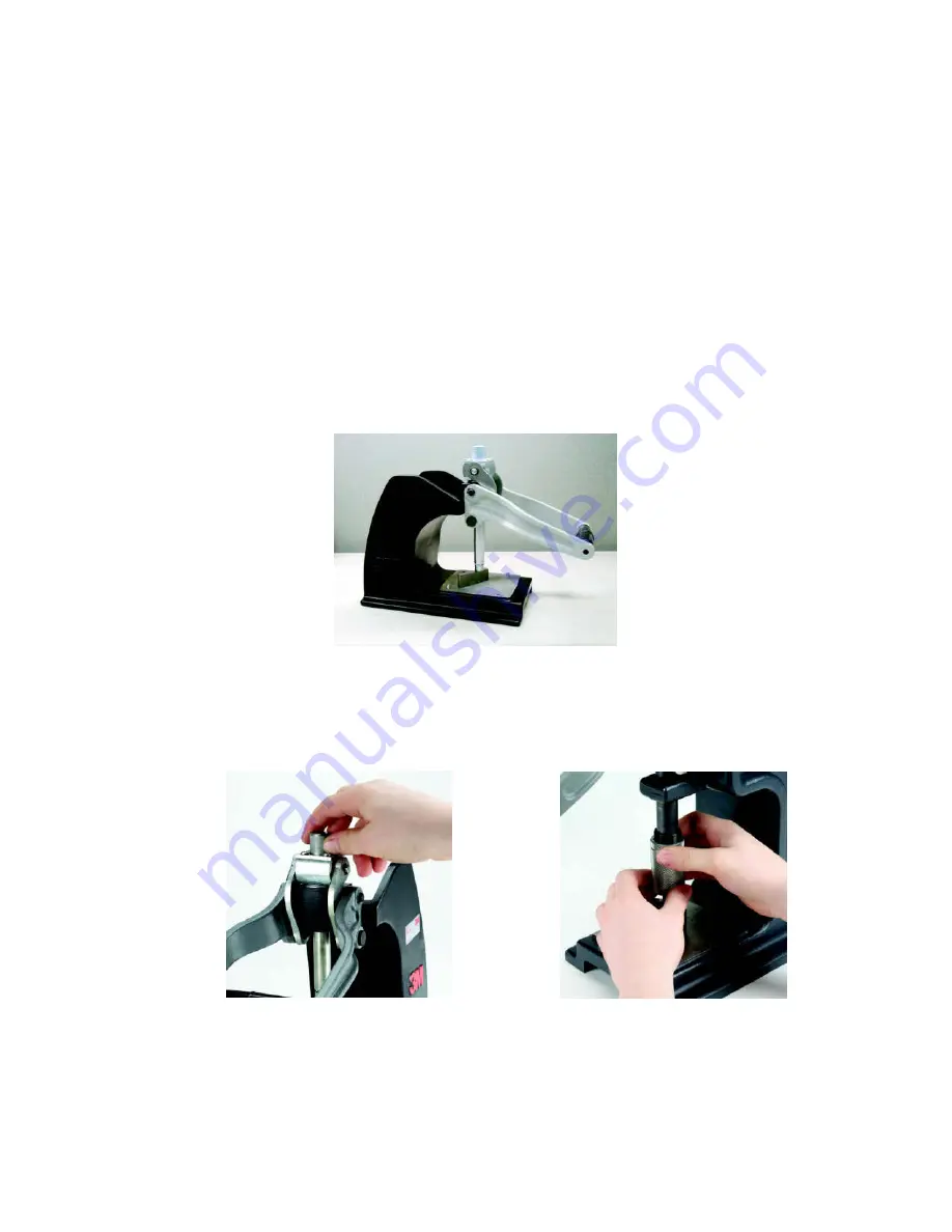
3.2


Lower the handle of the press until the handle casting makes contact with the 
press casting. (See Figure 2) 
 

3.3


Place the shut height gauge across the press base. (See Figure 2) 


Figure 2 


3.4


Rotate the shut height to lower or raise adjustment feature until the bottom of 
the shaft contacts the desired position on the shut height gauge. (See Figures 3 
and 4) 


Figure 3 


Figure 4 


Содержание 45116

Страница 1: ...g e 1 8 3M Instruction Guide 3MTM Locator Plate 3443 81 XX 3D Printed Instructions for the assembly of 3MTM Ribbon Cable Wiremount Socket Assembly 451 Series Instruction Guide March 2022 78 9102 1086...

Страница 2: ...1K Shut Height Setting 3MTM Assembly Press 3640 3316 3MTM Assembly Press 3335 45104 3443 81 04 3442 9 7 7 5 45106 3443 81 06 3442 9 7 7 5 45108 3443 81 08 3442 9 7 7 5 45110 3443 81 10 3442 9 7 7 5 45...

Страница 3: ...he press shaft and the 3MTM Assembly Press 3830 is self adjusting 3 1 The shut height adjustment is made from the base of the assembly press without the locator plate or platen in place 3 2 Lower the...

Страница 4: ...dd platen by positioning it parallel with the connector body and cover See Figure 9 Figure 5 4 0 Procedures for Cable Preparation Before assembly of the connector can take plate the cable must be prep...

Страница 5: ...ying the pin 1 indicator is in the correct position See Figure 8 Figure 8 5 2 Bring the handle of the press down until the IDC s press into cable and the connector fully seats into the cover See figur...

Страница 6: ...6 8 Figure 10 Metal fixture shown 6 0 Strain Relief Attachment 6 1 Fold the cable back over the cover See Figure 11 Figure 11 6 2 Place the strain relief in the connector over the cable sliding the s...

Страница 7: ...Instruction Guide 3MTM Locator Plate 3443 81 XX 3D Printed P a g e 7 8 6 3 Press the strain relief down until the strain relief snaps into the correct position on the connector See Figure 13 Figure 1...

Страница 8: ...ct and determining whether it is fit for a particular purpose and suitable for user s method of application Warranty Limited Remedy and Disclaimer Unless an additional warranty is specifically stated...

Отзывы: