


16
Adjustments
(continued)
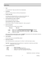
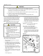
Tape Leg Length
1. Remove and retain two hex head screws and
remove the brush from normal position “A” on
side frame.
2. Remount and secure brush in position “A-A”
on side frame forward of normal location using
original fasteners.
3. Remove cut-off bracket extensions from position
"B".
4. Remount cut-off bracket extensions in forward
position “B-B”.
5. Remove and retain the one-way tension roller
assembly from slot “C” in frame.
6. Remount tension roller assembly near top of slot
“C-C” in frame using original fasteners.
7. Adjust tension roller according to "Leading Tape
Leg Length Adjustment" above.
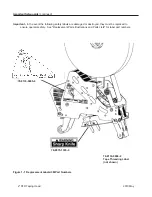
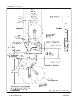
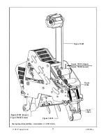
Leading Tape Leg Length Adjustment – Figure 5-6
The one-way tension roller position is adjustable to
control the leading tape leg length.
Moving this roller farther away from the box top or
bottom surface will decrease the leading leg length.
Moving it closer to the box top or bottom surface will
increase the leading leg length.
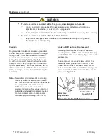
Changing Tape Leg Length from 70 to 50mm [2-3/4
TO 2 INCHES]
–
Figure 5-7
Note –
When changing tape leg length, both
upper and lower heads must be adjusted
to apply the same leg lengths.
Figure 5-6 – Leading Tape Leg Length
Figure 5-7 – Changing Tape Leg Length
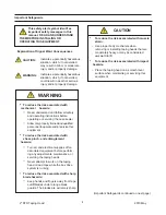
WARNING
•
To reduce the risk associated with
shear, pinch, and entanglement
hazards:
-
Turn air and electrical supplies off
associated equipment before perform-
ing any adjustments, maintenance, or
servicing the machine or taping heads.
- Never attempt to work on the taping
head or load tape while the box drive
system is running
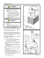
WARNING
•
To reduce the risk associated with sharp
blade hazards:
-
Keep hands and
fi
ngers away from tape
cutoff blades under orange blade guards.
The blades are extremely sharp
One-Way
Tension
Roller
Tape Leg
50 or 70mm ± 6mm
[2 or 2-3/4in. ± 1/4in.
One-Way
Tension Roller
Assembly
Slot C-C
Slot C
Position A-A
Position A
Position B-B
Position B
Brush
Cut-Off
Bracket
Extension
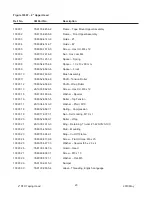
2" STD Taping Head
2010 May
Содержание 39600
Страница 4: ...THIS PAGE IS BLANK ...
Страница 6: ...THIS PAGE IS BLANK ...
Страница 8: ...8 THIS PAGE IS BLANK ...
Страница 10: ...THIS PAGE IS BLANK ...
Страница 48: ...36 THIS PAGE IS BLANK ...
Страница 50: ...38 THIS PAGE IS BLANK ...
Страница 52: ...40 THIS PAGE IS BLANK ...
Страница 53: ...41 16 TECHNICAL DIAGRAMS 16 1 Electric Diagram 2011 February 800at NA ...
Страница 56: ...44 THIS PAGE IS BLANK ...
Страница 58: ...46 2011 February 800at NA 800at Figure 10440 ...
Страница 60: ...48 2011 February 800at NA 800at Figure 3269 ...
Страница 62: ...50 2011 February 800at NA 800at Figure 5350 1 ...
Страница 64: ...52 2011 February 800at NA 800at Figure 5817 ...
Страница 66: ...54 2011 February 800at NA 800at Figure 6162 1 ...
Страница 68: ...56 2011 February 800at NA 800at Figure 6162 2 OPTIONAL ...
Страница 70: ...58 2011 February 800at NA 800at Figure 6163 1 ...
Страница 72: ...60 800at 2011 February 800at NA Figure 6163 2 Rear ...
Страница 78: ...66 Figure 6165 800at 2011 February 800at NA ...
Страница 80: ...Figure 6166 800at 2011 February 800at NA ...
Страница 82: ...70 THIS PAGE IS BLANK ...
Страница 84: ......
Страница 86: ...THIS PAGE IS BLANK ...
Страница 88: ...THIS PAGE IS BLANK ...
Страница 92: ...2 THIS PAGE IS BLANK ...
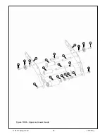
Страница 114: ...24 2 STD Taping Head 2010 May 2 1 5 4 6 15 14 12 13 12 11 10 4 7 3 15 8 16 9 9 8 16 Figure 10393 Upper and Lower Heads ...
Страница 116: ...26 2 STD Taping Head 2010 May 26 Figure 10387 Upper Head 9 9 1 9 4 5 3 8 7 9 9 2 9 10 11 ...
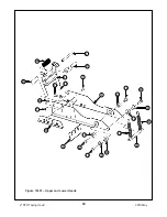
Страница 118: ...28 2 STD Taping Head 2010 May 28 Figure 10395 Upper and Lower Heads 4 2 1 6 3 3 5 6 4 5 ...
Страница 126: ...2 STD Taping Head 2010 May 36 Figure 10389 Lower Head 9 11 7 2 3 8 5 4 1 9 9 10 9 9 9 ...
Страница 128: ...38 THIS PAGE IS BLANK ...
Страница 129: ...39 ...
Страница 130: ...40 ...


