3M Two Hand 6 in. ROS
2
Revision 052209
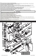
To reduce the risk of all hazards associated with vibration:
• If any physical hand/wrist discomfort is experienced, work should be stopped promptly to seek medical attention. Hand, wrist and arm
injury may result from repetitive work, motion and overexposure to vibration.
To reduce the risks associated with loud noise:
• Always wear protection for eyes, ears, and respiratory protection while operating this product. Follow your employer’s safety policy for
PPE’s and/or ANSI Z87. or local/national standards for eyewear and other personal protective equipment requirements.
To reduce the risk associated with fire or explosion:
• Do not operate the tool in explosive atmospheres, such as in the presence of flammable liquids, gases, or dust. The abrasives are able to
create sparks when working material, resulting in the ignition of the flammable dust or fumes.
• Refer to MSDS of material being worked as to potential for creating fire or explosion hazard.
To reduce the risk associated with hazardous dust ingestion or eye/skin exposure:
• Use appropriate respiratory and skin protection, or local exhaust as stated in the MSDS of the material being worked on.
To reduce the risk associated with hazardous voltage:
• Do not allow this tool to come into contact with electrical power sources as the tool is not insulated against electrical shock. .
To reduce the risk associated with skin abrasion, burns, cuts, or entrapment:
• Keep hands, hair, and clothing away from the rotating part of the tool.
• Wear suitable protective gloves while operating tool.
• Do not touch the rotating parts during operation for any reason.
• Do not force tool or use excessive force when using tool.
To reduce the risk associated with whipping or hazardous pressure-rupture:
• Ensure supply hose is oil resistant and is properly rated for required working pressure.
• Do not use tools with loose or damaged air hoses or fittings.
• Be aware that incorrectly installed hoses and fittings might unexpectedly come loose at any time and create a whipping/impact hazard.
To reduce the risk associated with fly off of abrasive product or parts:
• Use care in attaching abrasive product and mounting hardware; following the instructions to ensure that they are securely attached to the
tool before use or free-spinning.
• Never free spin the tool or otherwise allow it to be started unintentionally.
• Never point this product in the direction of yourself or another person, or start tool unintentionally.
• Never over-tighten accessory fasteners.
CAUTION!
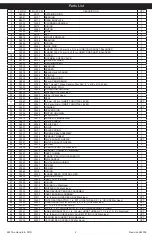
Parts Page
69
63
64
SYSTEM
VACUUM
FOR CENTRAL
TO VACUUM
62
68
67
1
2
56
3
4
57
58
5
6
7
9
10
11
12
13
17
16
15
14
18
19
20
21
22
23
24
25
26
27
28
29
30
32
31
33
34
70
59
52
8
41
42
43
44
46
45
35
36
47
48
37 38
25
49
39
51
66
51 53 54 55
51
40
60
61
50
52
51
65
ENG APP / DATE
CKD BY / DATE
PERMISSION OF X'POLE PRECISION TOOLS INC. IS PROHIBITED.
STD TOL
0.05
TOOLS INC.
NA
PROPERTY OF X'POLE PRECISION TOOLS INC. ANY REPRO-
SEE BOM
11/21/08
11/21/08
PWH
DUCTION IN PART OR AS A WHOLE WITHOUT THE WRITTEN
.XX +/-
XPD0056
ANGLES +/-
0.1
RAG
NA
XX/XX +/-
0.5°
X'POLE
PRECISION
P/N
TITLE
DRWN BY / DATE
MATERIAL
PROPRIETARY AND CONFIDENTIAL
.X +/-
THE INFORMATION CONTAINED IN THIS DRAWING IS THE SOLE
.XXX +/-
3M 6 in. (150 mm) 12,000 RPM
TwoHAND™ ROS PARTS PAGE
REVISION RECORD
R
DESCRIPTION / DATE
A
-RELEASE FOR PRODUCTION
RAG 11/21/08 PWH 11/21/08
B
-ITEM 51: P/N XPC0210 WAS XPB0454
-XPA1488 AND XPA1490 WERE NOT
REMOVED
-XPA1485, XPA0033, XPA0027, XPB0092 AND
XPB0123 WERE NOT ADDED
RAG 02/06/09 PWH 02/07/09
C
-ITEM 13: XPB0189, XPB0205, XPB0206, AND
XPB0207 WERE NOT REMOVED
-ITEM 30: XPA2074 WAS NOT REMOVED
-ITEM 48: XPA2173 WAS NOT REMOVED
-ITEM 49: XPA2172 WAS NOT REMOVED
-ITEM 60: XPA1962 WAS NOT REMOVED
-TORQUE SETTINGS CHART: 51 WAS 52,
52 WAS 53, AND 61 WAS 63
RAG 02/19/09 MDR 02/20/09
D
-ITEM 66: XPA1782 WAS XPA0033
-ITEM 67: XPA0027 WAS NOT REMOVED
-ITEMS 67 THRU 70: ITEM NUMBERS DID
NOT DECREASE BY ONE
RAG 02/23/09 MDR 02/23/09
1
VACUUM BAG FOR 3M
XPA1434
70
1
VACUUM BAG INSERT
XPC0109
69
1
1 in. DOUBLE BAG VACUUM FITTING
XPB0123
68
Y
T
Q
N
O
I
T
P
I
R
C
S
E
D
N
/
P
T
I
1
G
N
I
R
G
N
I
N
I
A
T
E
R
L
A
N
R
E
T
X
E
0
4
0
0
A
P
X
1
1
S
D
L
E
I
H
S
2
-
G
N
I
R
A
E
B
8
X
6
2
X
0
1
1
2
0
0
A
P
X
2
1
E
T
A
L
P
D
N
E
R
A
E
R
7
1
0
0
B
P
X
3
1
Y
L
B
M
E
S
S
A
R
E
D
N
I
L
Y
C
m
m
0
.
6
3
X
m
m
0
.
0
5
Ø
1
4
4
0
A
P
X
4
1
G
N
I
R
-
O
m
m
0
.
2
x
m
m
5
2
4
0
0
A
P
X
5
1
R
O
T
O
R
D
E
N
I
H
C
A
M
R
O
T
O
M
m
m
6
3
x
m
m
0
.
0
5
Ø
8
1
1
0
B
P
X
6
5
R
O
T
O
M
m
m
0
.
6
3
x
m
m
0
.
0
5
Ø
R
O
F
E
N
A
V
5
4
4
0
A
P
X
7
2
Y
E
K
F
F
U
R
D
O
O
W
m
m
3
1
x
m
m
3
1
4
0
0
A
P
X
8
1
E
T
A
L
P
D
N
E
T
N
O
R
F
6
1
0
0
B
P
X
9
1
S
D
L
E
I
H
S
2
-
G
N
I
R
A
E
B
8
X
8
2
X
2
1
9
1
0
0
A
P
X
0
1
1
G
N
I
R
-
O
m
m
1
.
3
x
m
m
4
.
9
3
5
4
0
0
A
P
X
1
1
1
G
N
I
R
K
C
O
L
1
0
0
0
A
P
X
2
1
13
XPB0187 TwoHAND 150 x 5.0 mm (6 x 3/16 in.) ORBIT ROS AirSHIELD™ SHAFT
BALANCER
1
13
XPB0188 TwoHAND 150 X 10 mm (6 x 3/8 in.) ORBIT ROS AirSHIELD™ SHAFT
BALANCER
1
1
R
E
T
L
I
F
2
2
1
0
A
P
X
4
1
1
E
V
L
A
V
K
C
E
H
C
L
L
I
B
K
C
U
D
1
2
1
0
A
P
X
5
1
1
R
E
N
I
A
T
E
R
E
V
L
A
V
0
2
1
0
A
P
X
6
1
1
G
N
I
R
G
N
I
N
I
A
T
E
R
).
ni
2
3
/
5
1
(
m
m
9
.
1
1
0
9
0
0
A
P
X
7
1
18
XPA0751 12 x 32 x 15.9 DOUBLE ROW ANGULAR CONTACT BEARING - 1 SEAL
1
1
K
H
T
2
.
0
x
D
O
0
.
2
2
x
D
I
1
.
2
1
R
E
C
A
P
S
7
6
7
1
A
P
X
9
1
1
R
E
H
S
A
W
E
L
L
I
V
E
L
L
E
B
4
2
0
1
A
P
X
0
2
1
E
L
D
N
I
P
S
8
0
2
0
B
P
X
1
2
1
G
N
I
R
G
N
I
N
I
A
T
E
R
5
2
0
1
A
P
X
2
2
1
D
E
R
5
8
4
S
M
P
-
M
3
R
O
F
H
C
N
E
R
W
D
A
P
m
m
4
2
7
7
7
1
A
P
X
3
2
24
NA
1 Pad Supplied With Each Tool (Type Determined By Model)
1
2
D
E
R
5
8
4
S
M
P
-
G
U
L
P
D
E
D
A
E
R
H
T
8
M
5
5
9
1
A
P
X
5
2
1
G
N
I
S
U
O
H
M
U
U
C
A
V
M
3
H
R
m
m
0
.
6
3
9
8
3
0
B
P
X
6
2
1
)
s
e
ni
h
c
a
M
V
C
&
V
N
(
T
R
E
S
N
I
R
E
L
F
F
U
M
2
3
0
0
A
P
X
7
2
1
)
s
e
ni
h
c
a
M
V
C
&
V
N
(
L
A
E
S
G
N
I
S
U
O
H
P
O
T
8
1
2
1
A
P
X
8
2
1
L
A
E
S
G
N
I
S
U
O
H
R
O
T
O
M
m
m
0
.
6
3
0
9
2
0
B
P
X
9
2
30
XPA2075 3M ROS 12,000 RPM 5.0 mm (3/16 in.) ORBIT THROTTLE LEVER - TwoHAND
1
30
XPA2076 3M ROS 12,000 RPM 10.0 mm (3/8 in.) ORBIT THROTTLE LEVER - TwoHAND
1
T
P
O
C
5
8
4
S
M
P
-
R
E
G
N
A
H
D
N
A
H
o
w
T
4
5
9
1
A
P
X
1
3
2
G
N
I
R
R
E
C
A
P
S
5
6
8
1
A
P
X
2
3
33
XPB0356 36.0 mm DIE-CAST MACHINE MOTOR HOUSING W/SIDE HANDLE
MOUNTING STUDS
1
1
N
I
P
G
N
I
R
P
S
R
E
D
N
I
L
Y
C
4
0
0
0
A
P
X
4
3
1
Y
L
B
M
E
S
S
A
M
E
T
S
E
V
L
A
V
5
5
6
0
A
P
X
5
3
1
E
V
E
E
L
S
E
V
L
A
V
5
1
0
0
A
P
X
6
3
1
T
A
E
S
E
V
L
A
V
9
0
0
0
A
P
X
7
3
1
E
V
L
A
V
7
0
0
0
A
P
X
8
3
1
G
N
I
R
P
S
E
V
L
A
V
4
1
0
0
A
P
X
9
3
1
Y
L
B
M
E
S
S
A
L
A
E
S
E
N
I
L
R
I
A
0
3
7
0
A
P
X
0
4
1
T
E
K
S
A
G
T
S
U
A
H
X
E
0
0
5
0
A
P
X
1
4
1
E
L
Z
Z
O
N
T
S
U
A
H
X
E
V
G
S
R
O
T
O
M
m
m
0
.
6
3
1
8
1
0
B
P
X
2
4
1
E
L
Z
Z
O
N
T
S
U
A
H
X
E
V
C
/
V
N
2
8
1
0
B
P
X
3
4
3
W
E
R
C
S
P
A
C
D
A
E
H
N
O
T
T
U
B
T
E
K
C
O
S
X
E
H
8
X
4
M
4
6
6
0
A
P
X
4
4
1
)
s
e
ni
h
c
a
M
V
C
&
V
N
(
P
M
A
L
C
G
N
I
B
U
T
6
1
5
0
A
P
X
5
4
1
)
s
e
ni
h
c
a
M
V
C
&
V
N
(
G
N
I
B
U
T
T
S
U
A
H
X
E
7
1
5
0
A
P
X
6
4
1
G
N
I
B
U
T
T
E
L
N
I
1
1
5
0
A
P
X
7
4
1
D
E
R
5
8
4
S
M
P
-
D
U
O
R
H
S
E
L
O
H
-I
T
L
U
M
"
6
D
N
A
H
o
w
T
1
2
1
2
A
P
X
8
4
T
P
O
E
L
D
N
A
H
E
D
I
S
M
3
0
6
9
1
a
p
x
9
4
1
E
L
O
H
E
L
D
N
A
H
E
D
I
S
/
W
G
N
I
S
U
O
H
Y
E
R
G
H
L
m
m
0
.
6
3
0
1
2
0
C
P
X
0
5
5
K
C
A
L
B
m
m
5
1
X
0
.
4
M
X
R
O
T
D
A
E
H
N
O
T
T
U
B
,
W
E
R
C
S
8
9
3
1
A
P
X
1
5
7
K
C
A
L
B
m
m
0
3
X
0
.
4
M
X
R
O
T
D
A
E
H
N
O
T
T
U
B
,
W
E
R
C
S
0
3
4
1
A
P
X
2
5
1
G
N
I
R
-
O
m
m
5
.
1
x
m
m
9
3
4
0
0
A
P
X
3
5
1
D
E
R
5
8
4
S
M
P
-
L
O
R
T
N
O
C
D
E
E
P
S
D
N
A
H
o
w
T
3
5
9
1
a
P
X
4
5
1
G
N
I
R
G
N
I
N
I
A
T
E
R
L
A
N
R
E
T
N
I
9
3
0
0
A
P
X
5
5
1
G
N
I
R
E
V
I
T
P
A
C
T
E
L
N
I
0
1
5
0
A
P
X
6
5
1
G
N
I
R
-
O
m
m
8
7
.
1
x
m
m
6
.
7
9
0
5
0
A
P
X
7
5
1
)
s
e
ni
h
c
a
M
V
C
&
V
N
(
G
N
I
R
-
O
8
2
6
0
A
P
X
8
5
2
)
s
e
ni
h
c
a
M
V
C
&
V
N
(
R
E
L
F
F
U
M
6
7
7
0
A
P
X
9
5
60
XPA1965 INLET/EXHAUST END CAP ASSEMBLY FOR SGV AND CV MACHINES
1
1
Y
L
B
M
E
S
S
A
G
N
I
H
S
U
B
T
E
L
N
I
T
P
N
8
1
-
4
/
1
3
1
0
0
A
P
X
1
6
1
)
s
e
ni
h
c
a
M
V
G
S
(
™
D
N
A
H
o
w
T
-
L
A
E
S
E
S
O
H
)
m
m
8
2
(
.
ni
1
3
2
6
0
A
P
X
2
6
63
XPA1669 3M™ FILTER BAG ADAPTOR, 1in EXT HOSE THREAD X 1in OD
1
1
)
ni
2
1
X
5
(
G
A
B
R
E
T
L
I
F
G
N
I
D
N
A
S
N
A
E
L
C
™
M
3
8
6
6
1
A
P
X
4
6
65
XPA1485 Ø 1 in. x 6 ft. VA
1
D
E
R
C
5
8
4
S
M
P
-
E
S
O
H
M
U
U
C
66
XPA1782 Ø 3/8 in x 4 ft AIR LINE WITH Ø 1/4 in COMPRESSION FITTINGS
1
67
XPB0092 HOSE END ADAPTER - 1 in./28 mm HOSE THREAD X 1 1/2 in. O.D.
1
ITEM NO. TORQUE SETTINGS in.-lbs (N-m)
12
55 - 65 (6.2 - 7.3)
44
21 - 30 (2.4 - 3.4)
51
27 - 30 (3.0 - 3.4)
52
29 - 33 (3.3 - 3.7)
61
60 - 72 (6.8 - 8.1)


