background image

6

6

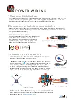
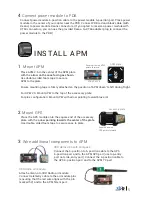
Connect APM to power module and PDB

Connect the power module six-position cable 

(red and black) to the APM PM port. Connect the 

PDB four-wire cable (multicolored) to the APM 

Outputs signal pins (top row). Ensure that the 

wire originating in the position on the PDB pins 

labeled M1 connects to the APM Output signal 

pin labeled 1, the M4 wire connects to position 

4, etc.

Locate the PDB four-wire cable (multicolored) and the power module six-position cable (red 

and black); thread these cables up through the slots in the APM plate where they can connect 

to the APM.

PDB to APM wiring

APM output 

pin positions

PDB wire 

positions

5

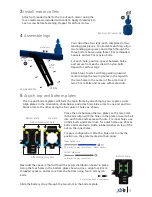
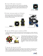
Attach accessory plate to APM plate

Place accessory plate on top of APM plate, and align 

the four 30 mm spacers with the four holes in the 

accessory plate. Secure accessory plate to spacers 

using four 5 mm nylon bolts.

APM plate

Accessory plate

30 mm 5 mm nylon bolt

4

Attach APM plate to top plate

Now we’ll attach the APM plate to the top plate. The APM plate 

connects to the ends of the four 30 mm bolts securing the inside 

holes of the arms. Place the four holes in the APM plate over the 

exposed 30 mm bolts on the top plate and secure with 30 mm 

threaded spacers.

30 mm bolt + 30 mm spacer

APM plate

7

Connect RC receiver to APM

When you’re ready to install an RC receiver module, use the provided four-wire and two-wire 

cables to connect to APM. Using the four-wire cable, connect the receiver’s channel pins 

to the corresponding APM Input signal pins. Use the two-wire cable to connect power and 

ground pins between APM and the receiver to provide power to the receiver.

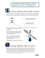
Complete plate assembly

Содержание Quad DIY Kit

Страница 1: ...QUAD D I Y K I T S Thank you for purchasing a 3DR Quad DIY Kit These instructions will guide you through assembling and wiring your new autonomous multicopter ...

Страница 2: ...th Deans or XT60 connectors Deans connectors male 4 6 position power module cable Phillips screwdriver small 5 5 mm 7 32 wrench Double sided foam mounting tape These instructions require some minor soldering If you re unfamiliar with soldering our friends at Sparkfun have some great tutorials that can get you started including this comic learn sparkfun com curriculum 42 For an example of exactly w...

Страница 3: ...l bM3MA 5 mm bolts and lock washers Position holes in the bottom of the motor over the two small holes on either side of the larger hole in top in the of the arm Secure with two 5 mm steel bolts with a metal lock washer on each bolt by accessing through the two large holes in the bottom of the arm Thread the motor cables through the arm using the hole in the side of the arm Repeat for all four arm...

Страница 4: ... slots in the bottom plate The top and bottom plates will form the main frame by attaching to your copter s arms Align plates in the orientation show below and attach two blue arms to one end and two black arms to the other using the four pairs of holes as shown Install motor collets 3 Motor collet assembly 25 mm bolt arm metal nut Outer holes use 4 Assemble legs Leg assembly Your Quad has four le...

Страница 5: ...to the black wire Shrink tubing over connections Add heat shrink and align wires to correct plugs Deans to ESC Negative Black Positive Red Soldered connectors 3 Connect ESCs to motors and PDB The diagram below indicates the number of each motor Starting with the motor labeled 1 connect the ESC three wire cable to the corresponding position on the PDB pins M1 for motor 1 M4 for motor 4 etc with ora...

Страница 6: ...nt APM to the top of the accessory plate For plus configuration Mount APM with arrow pointing toward blue arm Ensure arrow on APM points forward 3DR APM 2 6 2 6 3DR uBlox GPS with Compass Connect the 6 position to 5 position cable to the GPS 6 position port and to the APM GPS port use top entry port not side entry port Connect the 4 position cable to the GPS 4 position port and to the APM I2 C por...

Страница 7: ...the four 30 mm spacers with the four holes in the accessory plate Secure accessory plate to spacers using four 5 mm nylon bolts APM plate Accessory plate 30 mm spacer 5 mm nylon bolt 4 Attach APM plate to top plate Now we ll attach the APM plate to the top plate The APM plate connects to the ends of the four 30 mm bolts securing the inside holes of the arms Place the four holes in the APM plate ov...

Страница 8: ...ly secured is an important safety step Before flying use zip ties to secure ESCs to the frame Ensure that all wires are secured so that they cannot become entangled in spinning propellers but are not too tight around corners no hard 90 180 degree bends and do not pull on the APM or other components Always complete the pre flight checklist before takeoff copter ardupilot com wiki checklist Remove p...

Отзывы: