background image

91

3D SYSTEMS, INC

.

WARNING: FIRE AND EXPLOSION HAZARDS . COMBUSTIBLE DUST INSIDE .  METAL POWDERS ARE 

FLAMMABLE AND POTENTIALLY EXPLOSIVE, ESPECIALLY WHEN DISPERSED IN A CLOUD AND EXPOSED TO 

AN IGNITION SOURCE SUCH AS HEAT OR STATIC ELECTRICITY SPARK . OPERATORS AND SERVICE PERSONAL 

SHOULD AVOID DISTURBING POWDER (MANIPULATE CAREFULLY TO AVOID AS MUCH AS POSSIBLE 

SUSPENDING OF FINE PARTICLES) .

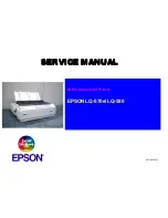
WARNING : FIRE AND EXPLOSION HAZARDS . PRESENCE OF METAL PARTICLE CONDENSATE INSIDE THE 

MANUFACTURING CHAMBER . HIGHLY COMBUSTIBLE . DO NOT VACUUM, DO NOT BLOW . USE DAMP COTTON 

CLOTH TO REMOVE THE METAL PARTICLE CONDENSATE .
WARNING : STATIC HAZARD . METAL PARTICLE CONDENSATES INSIDE THE PRINTER ARE HIGHLY 

COMBUSTIBLE AND SHOULD BE KEPT AWAY FROM SOURCES OF POTENTIAL IGNITION . WEAR ANTI-STATIC 

CLOTHING, ANTI-STATIC SAFETY SHOES, STAND ON GROUNDED ANTI-STATIC FLOOR PAD .

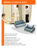
8.  Open the chamber door.

9.  Clean the sides of the manufacturing chamber with the use of a damp cotton cloth to neutralize any presence of the 

condensate (black particle aspect).

Caution : Wear disposable rubber gloves and leather gloves during this step .

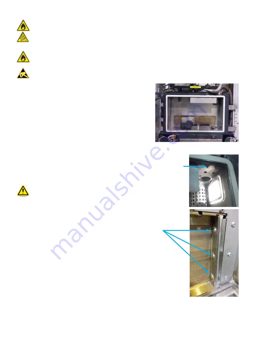
10.  On the right silicon wiper, remove the 3 screws fixing the wiper.

11.  Take out the wiper and separate the silicone blade to the subassembly.
12.  Remove the used silicone blade, and place the new one on its support.
13.  Gather the parts.
14.  Set the subassembly on the machine : get the silicone blade touching the protection strip, then screw tightly the screws 

removed at the step 10.

15.  Proceed in the same way to replace the left silicon wiper.
16.  Close the chamber door of the main cabinet, and tighten the captive screws.

CHC M5 x16 Screws

Metal particle 

condensate 

- Highly 

combustible

Содержание ProX DMP 200

Страница 1: ...ProX DMP 200 3D Production Printer User Guide Original Instructions Please refer back to http infocenter 3dsystems com product library prox 200 user guide for the most up to date user guide...

Страница 2: ...r ingestion 5 Powder skin contact 5 Powder eye contact 5 DMP Equipment Safety Features 6 Safety Interlocks 6 DMP System Response if an Interlock Fails 8 Limited Access and Barrier Shielding 8 Other Ac...

Страница 3: ...ng chamber door 21 Laser Safety Label Located on the optical rail 21 European Directives 22 European directive 89 686 CE in Europe 22 Operator safety 22 3 SYSTEM SPECIFICATION 22 The Prox DMP200 syste...

Страница 4: ...replacement process filters procedure 71 Process filter external filter 72 Preventive maintenance schedule 79 Every month maintenance 79 Every 3 months maintenance 80 Procedure to check the glove for...

Страница 5: ...d differently than stated in this manual The principal technical characteristics are mentioned on the table Fiber Laser P 300 W 1070 nm Layering system Adjustable Building volume 140 x 140 x 100 mm Me...

Страница 6: ...wders only Each metal powder should only be used after checking the information provided by the supplier the material safety data sheet MSDS and any applicable regulations Limitations relating to the...

Страница 7: ...t any components inside any DMP equipment enclosure Do not try to open any panel or door while a machine is running Do not access any area of the machine near the print chamber during printing Take no...

Страница 8: ...ry FIRE HAZARD Indicates potential fire can occur that could cause damage to equipment or personal injury EXPLOSION HAZARD Indicates potential explosion can occur due to combustible particles inside o...

Страница 9: ...user serviceable parts inside If electrocution occurs seek first aid and medical attention immediately Pushing the E stop button will de energize the equipment components and diffuse the hazardous sit...

Страница 10: ...THAT WILL PREVENT POTENTIALLY HAZARDOUS OPERATING CONDITIONS Safety Interlocks Safety interlock devices on the DMP equipment help prevent accidental laser exposure electrical shocks crush injuries bur...

Страница 11: ...7 3D SYSTEMS INC B Safety interlock switch on the right door C Safety interlock switch on the scanner head D Safety interlock switch on the airlock door...

Страница 12: ...limit access to the following Service areas such as cabinets and enclosures for electrical power and automation controls This prevents accidental exposure to electrical shock hazards Material areas su...

Страница 13: ...machine cannot be switched on ELECTRICAL SAFETY 3D Systems recommends explosion proof wiring for the room where the DMP is operating and where the materials are stored To prevent electrical shock DMP...

Страница 14: ...ty shoes The use of antistatic safety shoes is mandatory in any area where heavy items are handled This includes powder vessels and build platform In any area where powder is handled safety shoes with...

Страница 15: ...personnel entering those rooms must wear safety shoes with antistatic or conductive soles and antistatic or conductive outer garments If grounding through conductive flooring is impossible the use of...

Страница 16: ...G OPTIONS Finding Material Safety Information Use the Material Safety Information table to locate references and contacts for information on important material safety topics Read the SDS of the materi...

Страница 17: ...s that these powders form an immediate fire and explosion risk when exposed to moisture The end user is required to review the Safety Data Sheet for each material in your facility Always assume that a...

Страница 18: ...equipment INHALATION Avoid breathing powdered materials Always wear dust mask rated FFP3 N99 level protec tion or equivalent level protection Always provide adequate ventilation SHOP SAFETY Train oper...

Страница 19: ...at may become oxygen deficient make sure you comply with the following items If at any time you feel you are experiencing symptoms of oxygen deprivation leave the area immediately You have received ox...

Страница 20: ...Public Health Service Food and Drug Administration Center for Devices and Radiological Health CDRH and by IEC 60825 the International Electrotechnical Commission s Radiation Safety of Laser Products...

Страница 21: ...EMS INC SAFETY LABELS ON THE DMP SYSTEM Laser certification Identification with name plate A Machine nameplate B Laser certification statement Both are located at the rear of the control supply cabine...

Страница 22: ...ng Labels Airlock door Pinch Hazard Label Front of the scanner head Burn Hazard Label Oxygen sensor Behind the screen control panel Above the manufacturing chamber Inside the manufacturing chamber Adj...

Страница 23: ...19 3D SYSTEMS INC Warning labels Exhaust filter Warning labels Doors of the control supply cabinet Warning labels Rear of the control supply cabinet...

Страница 24: ...Laser Safety Labels Located on the scanner head trap door Laser Safety Labels Located on the scanner head Laser Safety Labels Located on the scanner head colimator side Laser Safety Labels Located on...

Страница 25: ...21 3D SYSTEMS INC Laser Safety Label Located under the airlock door Laser Safety Label Located on the manufacturing chamber door Laser Safety Label Located on the optical rail...

Страница 26: ...hould include cleaning inspection replacement Repairs must only be carried out by competent personnel Operator safety Components approved in accordance with standards EN 60204 1 safety of machinery Em...

Страница 27: ...ntrol panel see section D Screen control panel and external control panel on page 27 E Control supply cabinet see section E Control supply cabinet on page 28 F Stack light see section F Stack light on...

Страница 28: ...amber while being protected from the laser The chamber is equipped with a laser safety window 850nm 1100nm DLB5 IRLB8 CE EN207 The manufacturing chamber consists of 1 ROLLER PART OF THE LAYERING MODUL...

Страница 29: ...eometry enables to carry the powder from the feeding piston to the sintering piston Feeding piston This piston contains the volume of powder that will be used for sintering Its characteristics are giv...

Страница 30: ...t is fitted on the system to avoid particles and fumes from the sintering process being deposited onto the lens A gas flow sweeps permanently the underside of the lens trap this airflow is filtered us...

Страница 31: ...push button turns the machine on when it is powered up with the start up key switched to 1 4 STOP This button instantly stops all currently operating processes power heating element motor laser etc I...

Страница 32: ...s can be turned on or controlled even when the oxygen level is not at the required level laser lens cleaner blower and process filter valves The switch position can be viewed on the user interface see...

Страница 33: ...he button On Off then wait a few seconds UPS screen should switch off A message will ask to confirm the turn off select yes Turn OFF UPS1 Emerson press Enter to enter the setting menu then select MAIN...

Страница 34: ...r and maintaining the inerting process The airlock is located behind the front doors H Pneumatic data management This unit is located below the front doors of the printer It contains all the systems r...

Страница 35: ...s are trapped by the filter inside the vessel After the gas has gone through the filter media in the vessel it is pumped back into the machine via the top connection Clean Out The machine monitors con...

Страница 36: ...00 system follow the instructions outlined below The system must only be lifted by authorized people Make sure entire lifting rigging and supporting structure has been inspected and is in a good condi...

Страница 37: ...inet on page 28 5 Make sure that all doors are closed and emergency stop is not pushed 6 Switch the locking key to position 1 on the external control panel 2 7 Open the compressed air valve 3 and gas...

Страница 38: ...page 54 This button enables chamber lighting It is always available for use Machine off button see section Shutting printer down on page 69 Close Application button see section Closing opening PX Con...

Страница 39: ...The Preparation Menu allows user to prepare the printer to print a job and to unload the printed part This menu is composed by 8 successive steps Each step shows manual and automatic actions to be pe...

Страница 40: ...to be performed In this case confirm the pop up message to go directly to the next step The Plate unloading step includes both automatic and manual actions When automatic actions have been done manua...

Страница 41: ...is number will correspond to the sintering plate being loaded on the printer 3 Perform the actions 3 by using the available commands 4 and the external control panel Consult the section Plate preparat...

Страница 42: ...leted the zero sintering value is displayed 4 Click on Next 5 to go to the next step Step 5 Powder loading The Powder loading step is performed manually 1 Perform the actions 1 by using the available...

Страница 43: ...lacement required 1 Perform the actions 1 Consult the section Cleaning the laser optic system on page 62 for details on how to clean the lens 2 Click on Next 2 to go to the next step If filter replace...

Страница 44: ...acement is completed click on Reset 1 to reset the filter timer 3 Then perform the actions 2 consult the section Cleaning the laser optic system on page 62 for details on how to clean the lens 4 Click...

Страница 45: ...ProX DMP Manufacturing standalone software Inerting the manufacturing chamber and process filter Manufacturing file selection 1 Click on the folder icon to launch the file browser 1 2 Select the manu...

Страница 46: ...inert the manufacturing chamber 2 Once the O2 value is lower than the safety limit Start lens cleaner turbine button is enable Click on it 2 to activate the lens cleaner turbine the vessel valves will...

Страница 47: ...ases the _start_ layer by one and automatically fills the _end_ layer with the last layer value The button Aiming sets the laser in no power mode the laser will sinter without power with a red beam Th...

Страница 48: ...t not allowed Timer stops and resets When the printer is on the area A the Oxygen delay start window displays the current oxygen value and setpoint value the remaining time before the start of the job...

Страница 49: ...Oxygen tab paragraph of the section Configuration on page 47 Scanner head sensor state Base plate clamping state 1 Select Quit C then fix all warnings before continuing 2 Click on either Validate to c...

Страница 50: ...LENS CLEANER Turbine state of the lens cleaner blower turbine If green white the blower is operating not operating Setpoint setpoint of the blower operating in Differential pressure Outlet Pressure In...

Страница 51: ...nstructions on how to prepare to start a job and to remove the built part when job complete Adjuster level dedicated to advanced user no printer preparation wizard Access to the process settings with...

Страница 52: ...specific folders and do not affect the system operation Editing value For each tab the read only values are displayed in grey the editable values are displayed in black with the blue border To change...

Страница 53: ...section Preventive maintenance schedule on page 79 Powder management Name Powder used during the printing job To edit this field 1 Click on Specify D 2 The Powder Management window diplays see adjace...

Страница 54: ...If the setting is null this function is disabled The values are read only Editing these values requires higher access privilege see User level selection on page 47 Preparation tab This tab shows the...

Страница 55: ...pe_SerialNumber_PlateNumber Printer type e g ProX DMP200 Serial number e g 1122333 Plate number the number entered during the plate loading see section Step 4 Zero sintering on page 37 is linked to th...

Страница 56: ...52 3D SYSTEMS INC Manufacturing report...

Страница 57: ...xml formats click on the Export button D The selected tab will then be exported on the location you have specified 5 Optional to export all trackings files csv format click on the Export button E The...

Страница 58: ...Date indicates when the powder management feature has been set The border frame color of the powder name will be red if the powder type has been set as a reactive powder 3 GAS CONSUMPTION TRACKING Dis...

Страница 59: ...switch in service mode position Safety status of the safety of the machine and interlocks states open locked that can block a movement or a manufacturing start Laser type of laser status Ready Emissio...

Страница 60: ...t be closed Make sure to close the front doors so that the printer will be in READY mode i e operational Caution do not close the front doors on the gloves this may damage the gloves The gloves must b...

Страница 61: ...ck facing the operator side CLOSE airlock facing the chamber side Tools required A natural fiber brush for the cleaning process A tamping plate to compact the powder from the feeding piston A standard...

Страница 62: ...plate support 2 3 Degrease the upper face of the plate support and clean it with dry paper towel 4 Attach a sintering plate to the plate support 3 using the 4 screws The whole will be called build pl...

Страница 63: ...se the airlock door 13 Only for powders oxidizable materials purge the airlock for 5 minutes by using the screen control panel 14 Rotate the airlock to CLOSE position see Introduction on page 56 15 Pu...

Страница 64: ...d Implement the following operations Sieve the fresh powder once Place the fresh powder into a large tray in order to obtain a thin layer maximum 4cm Place the tray in the oven at 70 C for 24 hours in...

Страница 65: ...ock door 19 Rotate the airlock to CLOSE position 20 Close the front doors 21 If more powder is needed repeat from the step 3 Otherwise continue to next step Creating the powder bed Operations describe...

Страница 66: ...es off the lens 4 Hold the aerosol as upright as possible without shaking it Spray the aerosol once into free air in order to clear the gas tube of any dust that could damage the lens Avoid touching t...

Страница 67: ...mechanical stop is clean 6 13 Make sure the head lens support contact is clean 7 14 Ensure the cleanliness of the bellows and the lens cleaner diffuser 8 15 Close the head lens assembly making sure th...

Страница 68: ...fer to the Adjuster User Level appendix see User level selection on page 47 for details START A MANUFACTURING PROCESS WARNING THE MANUFACTURING CHAMBER AND PROCESS FILTER MUST BE INERTED BEFORE STARTI...

Страница 69: ...2 of the Preparation Assistant Proceed as indicated below 1 Click on the Preparation Menu button 2 Click on Validate to confirm 2 3 Follow the Preparation Assistant up to the step 2 Plate Unloading Th...

Страница 70: ...doors of the machine 15 Repeat steps from 8 to 13 until the sintering plate reaches its top position 16 Continue removing the excess of powder of the sintering plate 17 Remove the build platform the b...

Страница 71: ...en the two pistons 1 so that the roller does not get dirty when searching the zero of the sintering plate at the next manufacturing run 2 Remove powder from the top of the carriage 2 3 Move the carria...

Страница 72: ...en the glove doors 8 Remove the funnel 1 from the collecting cans location 9 Remove the collecting cans from their location 2 10 Close the collecting cans with their cans 3 11 Put the collecting cans...

Страница 73: ...r it will not be de energized To de energize the printer refer to the section Powering down the printer on page 69 POWERING DOWN THE PRINTER 1 The printer must be at first switched off see section Shu...

Страница 74: ...g its cleanliness At anytime Do not start the lens cleaner blower while the process filter is not connected to the printer Do not try to open the front doors without pressing the key button at first s...

Страница 75: ...datasheet SDS for that specific material Caution Personal Protective Equipment PPE must be used to protect the user against health or safety risks during working tasks Wear disposable rubber gloves an...

Страница 76: ...OOLS AND WEAR THE CORRECT PROTECTION THIS IS A TWO PERSON JOB Centering rings There are two types of centering ring used on the disposable process filter The first type is a standard centering ring th...

Страница 77: ...ter installation They will be used to close the filter during the replacement The procedure will indicate to store it for later use Caution the clean filter vessel is filled with argon to avoid water...

Страница 78: ...tion Assistant The graphic display of the closed filter valves is If valves are not closed corresponding graphic click on Can ister valves button on the control panel to close them Step 2 is performed...

Страница 79: ...er outlet port must be capped immediately after the outlet pneumatic valve is removed There may be a pressure difference when taking off the valve Do not be disturbed if you hear gas escaped this is n...

Страница 80: ...me temperatures 6 Dispose of vessel in accordance with all local regional national state and federal regulations Have the used filter vessel s picked up by hazardous waste transporter company the filt...

Страница 81: ...hould point to the filter vessel The tube will open the closing mechanism inside the vessel Proceed immediately to the filter outlet port connection in order to prevent too much air coming into the fi...

Страница 82: ...on the machine interface This will set the filter timer to zero and allow the Preparation Assistant to continue to the next step Step 8 Loading of the manufacturing file and inerting 12 The machine ha...

Страница 83: ...Front casings Clean X Back casings Clean X Exhaust filter Replace X Chiller Clean X Clamping filter Inspect Replace X X Gas filter Replace X Silicon wriper Replace X Chiller filter Replace X Cabinet f...

Страница 84: ...g chamber If rubber gloves become damaged fine dust can blow out into the environment Do not operate the machine with damaged glove If glove ripped or punctured during use dispose of it immediately an...

Страница 85: ...casings Procedure 1 Move the feeding piston and the sintering piston to the position 100mm 2 Switch off the printer see section Shutting printer down on page 69 3 Switch the locking key to position 0...

Страница 86: ...n cabinet As the fiber laser is still connected to the main cabinet move the supply cabinet gently Do not damage any cables 12 Remove the cover panel 2 at the rear of the main cabinet as indicated on...

Страница 87: ...ure with the use of a damp cotton cloth to neutralize any presence of the condensate black particle aspect 15 Remove any presence of powder on the enclosure with the use of a natural fiber brush and a...

Страница 88: ...se of powered air purifying respirator Procedure 1 Make sure the gas and purge are not activated 2 Open the door located below the front doors of the machine 1 and the left side door 2 3 Close the inp...

Страница 89: ...it with the filter guard on the machine Caution Make sure to re use the 2 O rings on top and bottom Caution Make sure to fit the filter element assembly on the correct position as indicated on the fo...

Страница 90: ...tag out label on the switch This will disconnect and isolate the printer from energy during the maintenance 4 Split up the control supply cabinet from the main cabinet the maintenance requires access...

Страница 91: ...nts inside the chiller evaporator compressor heat exchanger 12 Put back the side panels of the chiller 13 Put the chiller back to the control supply cabinet and secure it by tightening the screws remo...

Страница 92: ...the next step If the inspection does not reveal any presence of powder then fit back the cover plate removed previously The following steps must be performed if the filter element contains excessive m...

Страница 93: ...nscrewing it 2 Caution Wear disposable rubber gloves and leather gloves during the filter guard removal 4 Remove the filter element Dispose of it in accordance with all local regional national state a...

Страница 94: ...r level User level selection on page 47 Caution this maintenance will require to move the feeding piston Make sure not to perform the maintenance that might result in powder overflow inside the manufa...

Страница 95: ...ENTIAL IGNITION WEAR ANTI STATIC CLOTHING ANTI STATIC SAFETY SHOES STAND ON GROUNDED ANTI STATIC FLOOR PAD 8 Open the chamber door 9 Clean the sides of the manufacturing chamber with the use of a damp...

Страница 96: ...d tag out the printer position the main switch from the supply cabinet to position O then put a lock with a tag out label on the switch This will disconnect and isolate the printer from energy during...

Страница 97: ...ped with filter that must be replaced every 6 months Parts required Part number 5007129C00 quantity 1 Procedure 1 Open the left door of the cabinet 2 Remove the filter grid from the door 3 Replace the...

Страница 98: ...rall FFP3 respiratory protection anti static safety shoes 1 Switch off the printer see section Shutting printer down on page 69 2 Lock out and tag out the printer position the main switch from the sup...

Страница 99: ...the printer through the Adjuster level see User level selection on page 47 Caution presence of metal powder Do not use or manipulate any material without first reading the safety datasheet SDS for tha...

Страница 100: ...Start the draw layer 0 of the calibration plate without the red point 16 Repeat the previous step to be sure the draw will be well marked 17 Move up the sintering piston about 5 10mm for easier calib...

Страница 101: ...ection on page 47 4 Access to the Configuration tool 5 Go to the Optic menu 1 6 Click on the Import button 2 7 Select the new correction file then validate The new correction will replace the previous...

Страница 102: ...ility Directive 2014 30 EU of 14 October 2014 Statement about the relevant harmonized standards that have been used or statement about the specifications in relation to which conformity is declared St...

Страница 103: ...3D Systems Inc 333 Three D Systems Circle Rock Hill SC 29730 USA www 3dsystems com 2017 3D Systems Inc All rights reserved PN 80 D46 RevB...

Отзывы: