3D Histech Pannoramic DESK Скачать руководство пользователя страница 76

Pannoramic DESK 1.18.1 User’s Guide

6 Technical Data

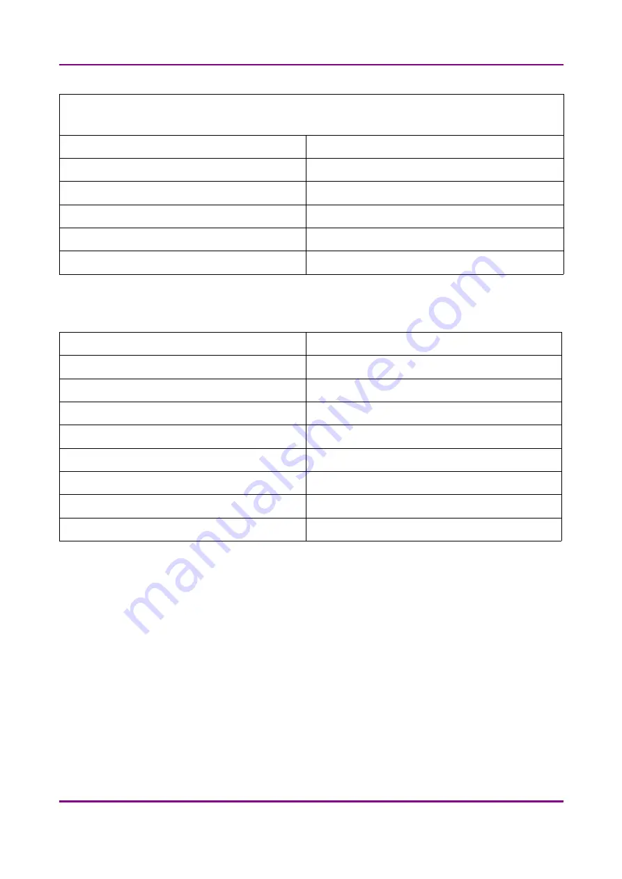
CIS VCC-FC60FR19CL camera

Global Shutter Type CMOS (Diagonal 15.930mm)

Pixel size

5.5µm × 5.5µm

Camera resolution

2048(H) × 2048(V) pixel

Frame rates

17fps / 34fps / 68fps / 135fps 

Bit-depth

10 bit

Pixel resolution with 20x objective and 1x C-mount adapter

0.24µm

Connection type

Dual CameraLink (full, 10 taps)

Control computer, minimum system requirements

Operating System

Microsoft Windows 7 SP1 64-bit EN

CPU

Intel Quad Core processor

RAM

4 GB

Hard disk

500 GB

Optical drive

DVD-RW

Display

96 dpi

Graphics

SXGA (1280 × 1024, True color)

Input devices

keyboard, mouse

Ports

2 x Fire Wire (1394 A & 1394 B), 4 x USB 2.0, GB Ethernet

May 29, 2014 - Rev. 1

3DHISTECH

 Ltd.

76

(

77

)

Содержание Pannoramic DESK

Страница 1: ...PD1 18 1 UG Rev1 Pannoramic DESK 1 18 1 User s Guide May 29 2014 Rev 1 ...

Страница 2: ...tions 16 1 2 3 Control Software 17 2 Installation 19 2 1 Control computer ports 19 2 2 Connectors and cables 20 3 Preparing Slides 21 3 1 Affixing Barcode Stickers to Slides 22 3 2 Inserting and Removing Slides 23 4 Software Description 26 4 1 Starting Exiting Pannoramic DESK Software Application 26 4 1 1 Starting the software 26 4 1 2 Exiting the software 26 4 2 Options 26 4 2 1 Barcode Settings ...

Страница 3: ...To Server 57 4 5 Using Profiles 62 5 Troubleshooting and Maintenance 63 5 1 Safety Information 63 5 1 1 Cleaning the device 63 5 1 2 Preventive maintenance 64 5 2 Troubleshooting 64 5 3 Maintenance 67 5 3 1 Removing the protective cover 67 5 3 2 Replacing the halogen lamp 68 5 3 3 Removing a slide 70 5 3 4 Transporting Pannoramic DESK 71 6 Technical Data 73 Index 77 May 29 2014 Rev 1 3DHISTECH Ltd...

Страница 4: ... IP are the sole properties of the 3DHISTECH Ltd 3DHISTECH Ltd is not liable for damage of whatever nature including but not limited to general or specific damage indirect damage consequential damage or incidental damage including the results of the analysis of the digitized slides for example change of health status related to erroneous diagnosis from the digitized slide s that stems from or is a...

Страница 5: ... KIND EXPRESSED IMPLIED OR OTHERWISE INCLUDING WITHOUT LIMITATION ANY WARRANTY OF MERCHANTABILITY OR FITNESS FOR A PARTICULAR PURPOSE IN NO EVENT SHALL SAM LEFFLER OR SILICON GRAPHICS BE LIABLE FOR ANY SPECIAL INCIDENTAL INDIRECT OR CONSEQUENTIAL DAMAGES OF ANY KIND OR FOR ANY DAMAGES WHATSOEVER RESULTING FROM LOSS OF USE DATA OR PROFITS WHETHER OR NOT ADVISED OF THE POSSIBILITY OF DAMAGE AND ON A...

Страница 6: ...101 Particular requirements for in vitro diagnostic IVD medical equipment EN 55011 1998 Group 1 Class A Limits and methods of measurement of radio disturbance characteristics of industrial scientific and medical ISM radio frequency equipment This product has been tested to the requirements of CAN CSA C22 2 No 61010 1 second edition including Amendment 1 or a later version of the same standard inco...

Страница 7: ...uch as F11 or the Ctrl M key combination Example Cross references within this document or to other documents Warning It might cause irreversible damage or harm to the user of the product or the product itself if this instruction is not followed Caution It might cause the product to not work properly if this instruction is not followed and alerts to a potential danger situation Note Calls attention...

Страница 8: ...nel All claims for warranty and warranty services will be null and void in any such case Warning Insert the power cord plugs only into a grounding outlet The protective action must not be rendered ineffective by extension cables without protective conductor The Pannoramic DESK has a built in protection which must not be rendered ineffective by extension cables without protective earth ground condu...

Страница 9: ...ver on Caution Avoid touching the lamp bulb Disconnect power plug and let the lamp cool down for about 15 minutes before replacing the lamp Crush hazard Never open the front door unless prompted accordingly by software When you open the door at any other time make sure not to reach with your hands into the instrument to avoid the risk of crushing your fingers Warning The front door is equipped wit...

Страница 10: ... accepted in cases of natural wear notably wear and tear parts or improper product handling The Product Manufacturer will refuse any liability in the event of damage resulting from faulty operation negligence or unauthorized intervention into the product notably from the replacement of product parts or the usage of accessory parts from other manufacturers Any such case will void the user s claim f...

Страница 11: ... Virtual Slide Slide A digital image of a thin glass plate on which specimens are mounted for microscopic study a dynamic interactive image that you can manage save magnify zoom name evaluate annotate mark and comment send to a colleague electronically for co operation or advice and so on May 29 2014 Rev 1 3DHISTECH Ltd 11 77 ...

Страница 12: ...C will highly affect the functionality of the scanner program 1 1 2 Features and Benefits The Pannoramic DESK offers world class brightfield whole slide scanning An outstanding 0 12 µm pixel resolution is achieved with the 40 0 95 NA equivalent to 80 magnification Carl Zeiss Plan Apochromat objective Key features of the Pannoramic DESK Scanner are 3MP camera for barcode reading and preview image I...

Страница 13: ... Description 1 1 3 Warning and Information Labels The following figure contains the labels used on the Pannoramic DESK main unit and the external mains power supply unit Figure 1 Warning and information labels May 29 2014 Rev 1 3DHISTECH Ltd 13 77 ...

Страница 14: ...1 Product Description 1 1 4 Base Unit The following figure shows the main parts of the base unit Figure 2 Main parts of the base unit 1 Protective cover 2 Protection rail 3 Scan camera 4 Sliding door May 29 2014 Rev 1 3DHISTECH Ltd 14 77 ...

Страница 15: ...he following hardware and software items 1 2 1 Pannoramic DESK system The following figure shows the main components of the Pannoramic DESK system Figure 3 Pannoramic DESK system overview 1 24 V external power supply unit 2 Pannoramic DESK base unit 3 Monitor 4 Mouse 5 Control computer 6 Keyboard May 29 2014 Rev 1 3DHISTECH Ltd 15 77 ...

Страница 16: ...nd monitor can vary depending on the product order Cameras Stingray F146C IRF Medical camera 1 CCD camera for normal brightfield application CIS VCC FC60FR19CL CMOS camera for high quality brightfield applications allowing fast scanning Camera adapters 0 63 adapter 1 adapter 1 6 adapter May 29 2014 Rev 1 3DHISTECH Ltd 16 77 ...

Страница 17: ... person Base Unit options Pannoramic DESK Basic Scan Option Fast Option base unit equipped with Stingray F146C IRF or CIS VCC FC60FR19CL camera for Brightfield scanning Objectives Carl Zeiss Plan Apochromat 20 NA 0 8 Carl Zeiss Plan Apochromat 40 Corr NA 0 95 Warning Do not change correction collar settings on 40 NA objective if you need it to be set contact customer service 1 2 3 Control Software...

Страница 18: ...noramic Viewer software fully functional Optional CaseCenter Pannoramic Viewer TMA module 3D Reconstruction module QuantCenter HistoQuant NuclearQuant MembraneQuant and DensitoQuant modules TumorBoard module E School Encoder May 29 2014 Rev 1 3DHISTECH Ltd 18 77 ...

Страница 19: ...n installation carried out by an unauthorized person Only qualified service assistants are allowed to install the hardware and software The product is ready for use after installation 2 1 Control computer ports The following figure shows the location of the connectors in order to enable easier transportation of the product for a short distance by disconnecting cables and detaching hardware compone...

Страница 20: ...computer Preview camera USB cable between scanner and control computer Stingray FireWire 1394 B cable between Stingray camera and control computer CIS a pair of CameraLink cables between CIS camera and control computer Video cable between monitor and control computer Power supply cable between 230V 110V and monitor Power supply cable between 230V 110V and control computer Power supply cable betwee...

Страница 21: ...lide when it is broken or its edges are not properly cut or grounded Using such slides can lead to injury Warning Ensure that no part of the mounted coverslip protrudes from the edges of the slide Use slides with completely dried embedding medium only Otherwise the coverslip can be shifted that makes slide insertion less reliable Not completely dried embedding might also influence the operation of...

Страница 22: ...arcode sticker 2 from the roll 2 Stick it on the colored label area 1 of the slide on the specimen side Caution Ensure that a marginal space of 1 2 mm remains on all sides between the sticker and the label area outer limits It is vital for barcode identification Do not let barcode sticker protrude from slide edges or stick on the coverslip surface 3 The thickness of the barcode sticker on the slid...

Страница 23: ... and its removal can lead to injury and contagion Broken slide can be removed only by a well trained person Figure 6 Inserting and removing a slide 1 Click in Pannoramic DESK control software The specimen holder moves to the load unload position 2 Open the slide insert door 1 by pushing it to the left Caution When opening the slide insert door fingers may be pinched during operation 3 Open the fix...

Страница 24: ...tagion Broken slide can be removed only by a well trained person 5 Close the fixing lever 2 by pushing it to the right so that it touches and therefore fixes the slide 6 Close the slide insert door 1 by pushing it to the right Caution When closing the slide insert door fingers may be pinched during operation Warning Never open the front door unless prompted accordingly by software When you open th...

Страница 25: ...he slide insert door 1 by pushing it to the left 3 Open the fixing lever 2 by pulling it to the left 4 Remove the slide 4 5 Insert another slide or close the fixing lever 2 and the door 1 Note The slide insert door is equipped with an interlock switch It automatically stops a running digitization process when the slide insert door is opened May 29 2014 Rev 1 3DHISTECH Ltd 25 77 ...

Страница 26: ...r successful initialization the program displays a Mode selection window Figure 7 Mode selection window The selection window displays Manual Brightfield scan mode for digitizing individual slides If you had exited this mode and want to reactivate it click Manual 4 1 2 Exiting the software If you close a mode or one of the options window the Mode selection window turns active again To exit the soft...

Страница 27: ...fining the barcode type foreground color black or white the color of the barcode and other settings you enable the Read Barcode option when using the control software Note You can only scan the barcode type that you have previously set If you want to read several barcode types you always have to set the current barcode type before reading it May 29 2014 Rev 1 3DHISTECH Ltd 27 77 ...

Страница 28: ...fine the barcode reading area by dragging the edges of the green square To check whether the barcode reading settings are correct display the barcode digits in the Barcode field by clicking Note If you did not set the barcode type correctly or there is no barcode in the barcode area the software will display the following error message Barcode detection unsuccessful There might be no barcode prese...

Страница 29: ...f you select Exclude check digit then the check digit number will also be analyzed as a barcode number Foreground Color You can select the following foreground color of the barcode area Black White Barcode Image Compensation Click Use barcode compensation image to use the previously created compensation image for scanning the label area The compensation image improves the effectiveness of barcode ...

Страница 30: ...ghtfield Compensation Figure 10 Brightfield Compensation Camera Selection This field displays the active camera Currently there is only one active camera for Brightfield mode Objective Selection The installed objective is selected for creating a new compensation image Preview Settings There might be specks or minor etches on the surface of the compensation slide that require modifying the threshol...

Страница 31: ...ed in some areas To create the compensation image s click Click the Stop button to interrupt the process The Progress bar at the bottom of the window displays the progress of the compensation image creation Image Browser panel Figure 11 Image Browser This function displays the created compensation image 4 2 3 Microscope Settings By moving the mouse over the buttons the software displays informatio...

Страница 32: ...can select the type and the magnification level of the objectives Camera type Select the correct camera type in Pos 1 Camera type then the software automatically loads the camera settings upon clicking the Test and Apply Camera Settings button Save settings by clicking the button May 29 2014 Rev 1 3DHISTECH Ltd 32 77 ...

Страница 33: ...ESK 1 18 1 User s Guide 4 Software Description Filter Settings Figure 13 Filter settings The settings on this panel apply to Fluorescent mode therefore irrelevant and inactive May 29 2014 Rev 1 3DHISTECH Ltd 33 77 ...

Страница 34: ...Pannoramic DESK 1 18 1 User s Guide 4 Software Description Camera Rotation Figure 14 Camera rotation May 29 2014 Rev 1 3DHISTECH Ltd 34 77 ...

Страница 35: ... not modify these settings yourself Service Figure 15 Service tab This tab contains control and maintenance functions Emergency Manual Slide Removal Position The specimen holder will be moved to a position where the slide can be removed manually after opening the cover see section 5 3 1 Removing the protective cover Slide Removed Manually Click this button to notify the software that you have remo...

Страница 36: ...Slide Scanning Finished Scanning Error Occurred For Slide Scanning Finished and Scanning Error Occurred you can define the external software by entering the file path in the Application box or by browsing for it by clicking If you define parameters in the Parameters box it will pass them to the software that it starts If no parameter is defined then the parameter will not be passed The default par...

Страница 37: ...users and also set the message body in the Message subject field by entering a text for example to inform recipients on the location of the scanner or the slide set you are working with Click Test to test settings by sending an e mail to the address defined in the E mail To field after you have finished to check their relevancy before applying them First click Setup to display the Messenger Setup ...

Страница 38: ...ages that come up after sending the e mail An e mail has been sent to the recipient An error has been occurred The e mail could not be sent Check parameters then retry If you have properly set messenger settings click OK then click Users in the Message Call section of the Event Call Settings window to address functions to the recipients that can be selected under the Send Message when field Figure...

Страница 39: ... quality settings You can also set profile settings here and start scanning in Brightfield Manual mode For more information on profiles see section 4 5 Using Profiles Figure 19 Main window of control software 1 Tab panel with scanner functions and settings 2 Scan camera live image display area 3 Preview image recorded by the preview camera 4 Preview image editor toolbar 5 Information area about th...

Страница 40: ...and that it rests perfectly horizontally on the stage To enter the slide name To enter the slide name manually type it into the Slide Name field To use the barcode as a slide name if a compatible barcode sticker is affixed on the slide click First the software automatically detects the barcode on the slide then the barcode string will be displayed in the Slide Name field You can also find the butt...

Страница 41: ... the current profile click Save To select an existing profile from the selection menu click Load To delete the current profile click Delete To access the Scan Options window click Note These settings are only applicable if you do not use profiles If you use profiles the settings stored in them are used 4 3 2 Scan Options window Figure 21 Scan options window May 29 2014 Rev 1 3DHISTECH Ltd 41 77 ...

Страница 42: ...e function is only available for products installed with Stingray camera It is not accessible for configurations installed with CIS camera Image fields will be saved with native pixel resolution If this function is disabled you will work with reduced pixel resolution These resolution differences are not really visible with the human eye what is important in this feature is the resulting smaller fi...

Страница 43: ...ver application see section 4 4 Scan To Server If you enable the Directory function the virtual slides will be digitized in the specified folder You can browse for the folder with the Browse button If you specify a folder that does not exist the software will create it All parameter inputs are saved for the next software session 4 3 3 Preview tab The Preview tab offers options for threshold settin...

Страница 44: ...sensitive scanning but it is possible that some of the smaller specimen areas will not be digitized Scan area inside the marker If the specimen cannot be identified as required for digitization for example weak contrast it can help to encircle completely the specimen with a black marker pen You have to draw a full circle with the pen to enable the detection Marker pen detection will make specimen ...

Страница 45: ...eas Warning Do NOT use Remove coverslip function on TMA slides The layout of TMA slides may mislead the detecting algorithm Fill holes in scan area If selected the holes inside the specimen will also be scanned Often these holes contain small sample objects that otherwise would not be scanned Remove specks If selected the scanner does not digitize objects smaller than the predetermined size This h...

Страница 46: ...d preview mask or TMA grid Use selection box If selected only the area inside the box is scanned It is useful if you only want to scan the area that is equivalent with the size of the coverslip so external specks will not be scanned 4 3 4 Preview area scanned by preview camera The preview image shows the area that will be digitized with a red and or an orange mask If the Use selection box is enabl...

Страница 47: ...ple areas that will not be scanned These areas are not digitized on the basis of their position for example they are outside the selection box They are detected by the selected threshold value Marker If Scan area inside the marker is selected in the Preview tab the preview camera detects the marker pen The inside areas appear in red color and will be digitized Areas scanned in This color is only d...

Страница 48: ...k on the area of interest on the preview image This will define the Live image that you can access from the Focus tab To display the original image created by the preview camera click To shrink or enlarge the preview image set the zoom level at the left Size selection box 100 600 To fit the preview image to the preview area click Fit Choose from the Scanned or the Not scanned option from the right...

Страница 49: ...e selection settings on the following four tabs Select tab Figure 29 TMA tool Select To create a new TMA object click New To select an existing TMA object click on the object name The selected object name will highlight To delete an existing TMA object click Delete Block tab Figure 30 TMA tool Block May 29 2014 Rev 1 3DHISTECH Ltd 49 77 ...

Страница 50: ...ropriate values with the arrows 3 Enter the distance between two spots on the X and the Y axis in µm in the Spot distance X µm and Spot distance Y µm fields or select the appropriate values with the arrows 4 Enter the average diameter of the spots in the Diameter of spots µm field or select the appropriate value with the arrows Grid tab The Grid tab displays the previously set grid settings Figure...

Страница 51: ... of the TMA selection spots that are displayed on the preview image To move the spots enter the pixel value in the Move field or use the arrows To rotate the spots enter the degree value in the Rotate field or use the rotation arrows Figure 32 TMA tool Move tab with preview May 29 2014 Rev 1 3DHISTECH Ltd 51 77 ...

Страница 52: ...1 User s Guide 4 Software Description Label area To rotate the label area by 180 select the Rotate image by 180 degrees checkbox Figure 33 Label area 4 3 5 Focus tab Figure 34 Focus tab May 29 2014 Rev 1 3DHISTECH Ltd 52 77 ...

Страница 53: ...uct as a traditional microscope Define the manual focus step size by adjusting the Step size slider Search for the sharpest focus on the current field of view automatically by clicking Multilayer mode Select Single layer option if you want to scan a single layer of the slide By choosing the Extended focus option the software selects the sharpest image from each focus level for each image field and...

Страница 54: ...e slide can be removed manually after opening the cover see section 5 3 1 Removing the protective cover Slide Removed Manually Click this button to notify the software that you have removed the slide manually Show images during scanning If you select this option you will be able to see the currently scanned image field during scanning in the live image display field This slows down digitization pr...

Страница 55: ...r live images The display field for live images displays images of the scan camera The live image is displayed if no current digitization process is running or Show images during scanning option is enabled Figure 37 Display field and toolbar for live images May 29 2014 Rev 1 3DHISTECH Ltd 55 77 ...

Страница 56: ...e bars Displays the magnifier window Activates red marking on overexposed pixels Recalculates exposure time useful if too many overexposed pixels were detected Calculates white balance only for color cameras Saves the current image as BMP or JPEG file Fast live mode live images are displayed with a frequency of at least 10 images second Normal live mode images are taken with the user specified exp...

Страница 57: ...e Available disk space of the information area of Current Slide Scan Progress You can interrupt a running digitization process by clicking This button is only enabled if a digitization process is in progress 4 4 Scan To Server The ScanToServer function is available for you to scan directly to a dedicated CaseCenter server To setup connection with a designated server follow the steps below 1 Click ...

Страница 58: ...then click Connect Figure 39 Scan to CaseCenter option 3 Type in or select the server address from the Connect to drop down list and give the User name and Password Activate the Secure connection option to enable HTTPS connection Click Connect when finished Figure 40 Server Log in window May 29 2014 Rev 1 3DHISTECH Ltd 58 77 ...

Страница 59: ... the Scan Options window Slide settings in the Scan To Server window 1 In the Routine work tab panel click the button 2 The Scan To Server window opens Figure 42 Scan To Server window Slide data is displayed in a form Upon activating the Read barcode if no name is defined on the list option the slide barcode will be read and set in the Barcode field If you do not want to use this option you can ty...

Страница 60: ... of the barcode will be displayed and set as slide name 123 Case and Block fields can be set this way as well if necessary NOTE When filling slide data fields press TAB to move to the next cell Figure 43 Profile selection in the Scan To Server window Profile can be added by selecting a list entry from the Profile drop down list Select a folder where the slide will be scanned to After clicking the ...

Страница 61: ...ically selected as scanning destination based on the CaseID containing slide and patient data stored on HIS LIS Therefore Slide name Folder Case and Block field data cannot be modified only a profile can be selected Figure 45 Scan To Server window during Barcode parsing Click Done when finished or Cancel to quit the Scan To Server window If you save the form slides will be scanned to server accord...

Страница 62: ...e ON OFF available if Stingray F146C camera is used Determination of the area to be scanned Use of automatic threshold specimen Use of specimen threshold value Use of marker pen threshold and specimen threshold values Remove coverslip function ON OFF Use of scan everything within marked area function ON OFF Filling of holes ON OFF Use of removing specks according to the set value ON OFF Use of sav...

Страница 63: ... effects damaging to health Decontaminate infectious materials after use Dust specks and humidity may decrease or harm the operating capability of the device Protect it with dust cover when not in use Switch the power off before covering it Avoid touching the lamp bulb Wait for about 15 minutes to allow the bulb to cool down and disconnect the power plug before changing the bulbs Defective devices...

Страница 64: ...ns for the Pannoramic products If any problem arises that does not have solution in this manual contact the service personnel The product does not start Power supply is interrupted 1 Make sure that the 24V external power supply is on 2 Check cable connections Control software has stopped Name of currently selected slide for digitization already exists and is open in Pannoramic Viewer Close virtual...

Страница 65: ...eplacing the halogen lamp Virtual slide is improperly focused almost across its entire surface Focus range enabled Disable Limiting focus range Poor image quality Imaging error for example chromatic aberrations Contact 3DHISTECH Service for support Warning Do not modify the camera driver settings as the default factory settings give the most accurate images Virtual slides show poor stitching in Pa...

Страница 66: ...tended focusing option if not required Z stack option is activated Deactivate the Z stack option if not required Image is out of focus Focus range limit is activated Deactivate the Limiting focus range option Focus range setting is incorrect Change focus range setting All individual images show a shading effect Algorithm failed to find empty image fields Capture a reference image with a blank slid...

Страница 67: ...To replace the halogen lamp or to perform other maintenance work and to interrupt a running digitization procedure because of slide jamming the protective cover of the Pannoramic DESK need to be removed in order to eliminate the problem Before removing the cover exit the control software switch off the 24 V power supply and disconnect the power cables Caution Only instructed persons or service tec...

Страница 68: ...hed maintenance or repair work reattach the cover Push it horizontally towards the basic unit 4 until the two protruding guide pins 6 fit into the corresponding recesses of the basic unit 4 Note that the rear part of the cover must be pushed over the top part of the blue basic unit 7 5 To lock the cover in place insert the screws again and fasten them Caution Make sure that no cables are squeezed ...

Страница 69: ...o the hole 5 on the heat sink body 7 Remove the lamp mount with the lamp 8 Remove the defective lamp 4 from the lamp mount 9 Insert a new bulb into its mount Warning Do not touch the bulb with your bare fingers Use a dry clean lint free cloth or gloves when inserting the bulb into the mount 10 Taking care that the two clamps 3 on the lamp mount are correctly aligned to the hole 5 on the heat sink ...

Страница 70: ...med slide cancel the running digitization process terminate the software session and turn the power off Any manipulation performed on a mechanical component must be followed by a complete device initialization routine software restart Figure 49 Removing a slide 1 Exit control software 2 Switch off power supply and disconnect power cable 3 Remove the cover see section 5 3 1 Removing the protective ...

Страница 71: ...over 8 Connect the power cable of the power supply to the power outlet and switch on the power supply 9 Launch control software 5 3 4 Transporting Pannoramic DESK The following procedure shows how to transport Pannoramic DESK Caution Do not lift or transport Pannoramic DESK by holding its protective covers Note The base unit does not have carrying handles for transporting One or two persons can ca...

Страница 72: ...DESK do the following 1 Turn power supply off and detach all cables 2 Transport Pannoramic DESK 3 After finishing transportation reestablish cable connections Caution Readjust camera angle if necessary after transporting and reinstalling the Pannoramic DESK May 29 2014 Rev 1 3DHISTECH Ltd 72 77 ...

Страница 73: ...upply approx 550 g Ambient conditions Transportation shipment packed Permissible ambient temperature 40 C to 70 C Storage Permissible ambient temperature 0 C to 60 C Permissible relative air humidity non condensing 75 Operation Permissible ambient temperature 10 C to 35 C Permissible relative air humidity 75 Altitude at installation site max 2000 m Atmospheric pressure 500 hPa to 1060 hPa Degree o...

Страница 74: ... Power consumption of the complete device 75 VA 24V external mains power supply unit Intended site closed room facilities Electrical protection class I Internal protection degree IP 20 Electrical safety in compliance with UL 2601 1 TÜV EN 60601 CE EN60601 1 2 2001 Over voltage category II Radio interference suppression in accordance with CISPR 11 EN 55011 class B Line input voltage 100 V AC to 240...

Страница 75: ...ing UPC A Numeric encoding DataMatrix Numeric encoding Alpha encoding AlphanumericPunc encoding AlphaNumeric encoding ASCII encoding IS08 encoding Maxicode Encoding mode 2 3 4 5 6 MicroPDF417 Standard encoding type PDF417 Standard encoding type QR QR code Model 1 2 encoding Scan cameras Stingray F146C IRF Medical camera 1 2 type progressive scan CCD Pixel size 4 65µm x 4 65µm Camera resolution 138...

Страница 76: ...lution with 20x objective and 1x C mount adapter 0 24µm Connection type Dual CameraLink full 10 taps Control computer minimum system requirements Operating System Microsoft Windows 7 SP1 64 bit EN CPU Intel Quad Core processor RAM 4 GB Hard disk 500 GB Optical drive DVD RW Display 96 dpi Graphics SXGA 1280 1024 True color Input devices keyboard mouse Ports 2 x Fire Wire 1394 A 1394 B 4 x USB 2 0 G...

Страница 77: ...8 52 53 54 62 65 66 H Halogen lamp 65 67 68 74 M Marker 44 47 62 P Pannoramic 6 Pannoramic DESK 6 8 9 10 12 13 15 17 19 23 25 26 64 67 71 72 Pannoramic Viewer 18 53 64 65 Preview 20 22 24 26 30 39 43 44 45 46 47 48 51 53 75 R RGB 56 S Scan 12 14 17 30 36 39 40 41 42 43 44 45 46 47 48 53 54 55 57 62 65 71 75 Scan To CaseCenter 43 Scan To Server 59 60 61 Scanner 6 30 45 ScanToServer 43 57 Stingray 1...

Отзывы: