


Setting Up Resilient Links
4-23
Viewing the Resilient Setup
With the Switch Management screen displayed,
choose the management level
Unit
and select the
RESILIENCE button.
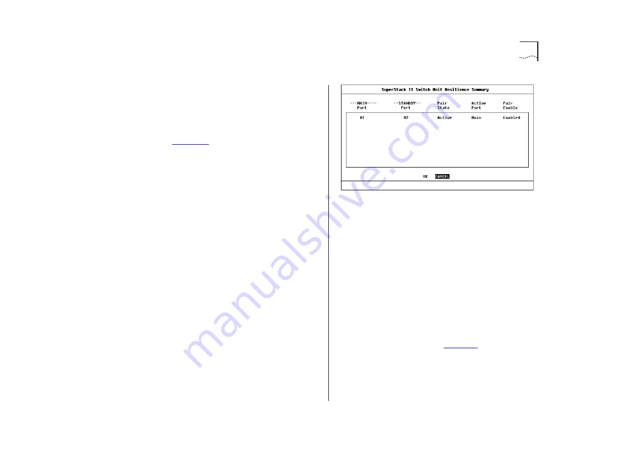
The Unit Resilience Summary screen is displayed as
shown in
. This screen shows the cur-
rent resilient link configuration for the unit, and
allows you to access the Port Resilience screen for
the resilient link pairs.
The screen contains the following:
MAIN Port
This read-only field displays the ID of
the port configured as the main port for the resilient
link pair.
STANDBY Port
This read-only field displays the ID
of the port configured as the standby port for the
resilient link pair.
Pair State
Active / Both Failed / Unknown / Not
Available
This read-only field displays the current
state of the resilient link pair:
■
Active
— The resilient link pair is enabled and
operating normally with both main and standby
ports capable of carrying traffic.
■
Both Failed
— Although the resilient link pair is
correctly configured, both links have failed. Check
for any loose connections or cable damage.
■
Unknown
— The network configuration has
changed and the resilient link pair no longer con-
forms to the rules.
■
Not Available
— The resilient link pair is disabled.
Figure 4-15
Unit Resilience Summary screen
Active Port
Main / Standby / Both Failed
This
read-only field displays which port in the resilient
link pair is currently carrying traffic:
■
Main
— The pair is operating in its normal state
with the main port carrying traffic.
■
Standby
— The main port has failed and the
standby port is carrying the traffic. You should
rectify the fault as soon as possible. If a main
port has a higher bandwidth than the standby
port, traffic is automatically switched back pro-
vided no loss of link is detected for two minutes.
Otherwise, switch the traffic back manually by
setting the Active Port field in the Port Resilience
screen (described on
) to Main.
■
Both Failed
— Both ports of the resilient link pair
have failed. This could be due to loose connec-
tions or cable damage.
Содержание SuperStack II Switch 3000 10/100
Страница 14: ...1 6 CHAPTER 1 GETTING STARTED Figure 1 2 Increasing port density with the Switch 3000 10 100 ...
Страница 15: ...Unit Overview Front 1 7 Unit Overview Front Figure 1 3 Switch 3000 10 100 front view ...
Страница 17: ...Unit Overview Rear 1 9 Unit Overview Rear Figure 1 4 Switch 3000 10 100 rear view ...
Страница 22: ...1 14 CHAPTER 1 GETTING STARTED ...
Страница 25: ...Configuration Rules with Full Duplex 2 3 Figure 2 1 Fast Ethernet configuration rules ...
Страница 79: ...Virtual LANs VLANs 5 7 Figure 5 5 VLAN configuration with a Switch 3000 10 100 as a basement switch ...
Страница 112: ...6 12 CHAPTER 6 STATUS MONITORING AND STATISTICS ...
Страница 128: ...C 6 APPENDIX C TROUBLE SHOOTING ...
Страница 129: ...D PIN OUTS Null Modem Cable 9 pin to RS 232 25 pin PC AT Serial Cable 9 pin to 9 pin ...
Страница 130: ...D 2 APPENDIX D PIN OUTS Modem Cable 9 pin to RS 232 25 pin RJ45 Pin Assignments ...
Страница 142: ...6 GLOSSARY ...


