


Handling the Module
The Module can be easily damaged by electrostatic
discharge. To prevent damage, observe the following:
Always wear an anti-static wristband connected to a
suitable earth point.
Do not remove the Module from its packaging until
you are ready to install it into a Switch.
Do not touch any of the pins, connections or
components on the Module.
Handle the Module only by its edges and front panel.
Always store or transport the Module in anti-static
packaging.
Installing the Module into a Switch
CAUTION:
This Module is not hot-swappable. Always
make sure that the Switch is powered down and
disconnected from the mains before installing or
removing a Module. Use the following instructions when
installing or removing a Module.
Each Switch has the facility to accept up to two
Expansion Modules, allowing Gigabit Ethernet or Fast
Ethernet connections. Modules can be inserted into either
Expansion Module slot.
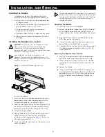
Figure 1
Inserting the Module into the Switch
To install the Module:
1
Ensure that the Switch is disconnected from the mains
power supply and that you are wearing an anti-static
wristband connected to a suitable earth point.
2
Undo the two screws securing the blanking plate at the
rear of the Switch using a suitable screwdriver. Do not
remove any other screws from the rear of the Switch.
3
Remove the blanking plate.
4
Hold the Module so that the text on the front panel is
upright and insert it into the Switch, ensuring the
connectors are fully engaged (see
Figure 1
). Make sure
the Module is pushed fully in.
5
Secure the Module by tightening the two captive screws
with a screwdriver.
Keep the blanking plate in a safe place. If you remove the
Module at any time, you must replace the blanking plate
to prevent dust and debris entering the Switch. Replacing
the blanking plate will also help circulate cooling air
through the Switch.
Activating the Module
1
Ensure that the Switch is powered-up.
2
Remove the protective stopper from the MT-RJ fiber port
on the Module. Squeeze the top and bottom of the
stopper between your thumb and forefinger then remove
it.
3
Plug the MT-RJ connector on the fiber cable into the
MT-RJ fiber port on the Module.
4
Connect the other end of the fiber optic segment to a
device fitted with a 1000BASE-LX connection.
5
Check the LEDs on the front of the Switch to ensure that
the Module is operating correctly. Refer to
“LEDs”
for
more information.
Removing the Module from a Switch
1
Ensure that the power supply and the fiber backbone
connection cables are disconnected from the Switch.
2
Undo the Module’s two captive screws with a suitable
screwdriver. Do not remove any other screws from the
Switch.
3
Remove the Module.
4
If you are not fitting another Module immediately, you
must replace the blanking plate to ensure that dust and
debris do not enter the Switch. Replacing the blanking
plate will also help circulate cooling air through the
Switch.
I
NSTALLATION
AND
R
EMOVAL
!
3
Содержание SuperStack 3 4300
Страница 8: ......


