background image


5

Wall Mount Installation


1


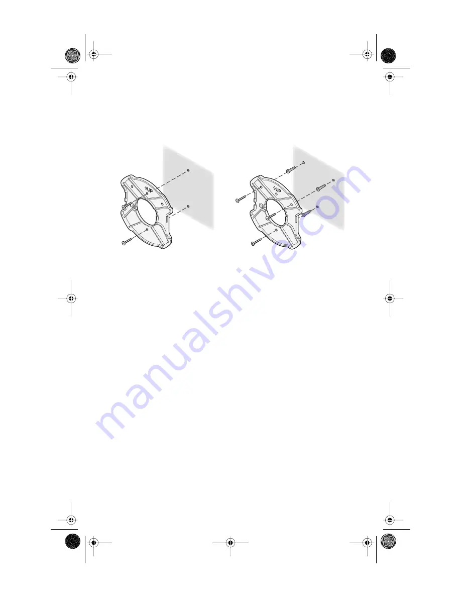
Install the mounting plate as shown in the following illustration, on either a stud 
(or other hard wall surface), or onto drywall.


Allow for a clearance of at least 25 cm (10 Inches) between the ceiling and the top of the 
mounting plate.


Make sure that “UP” is correctly oriented, and align the mounting plate screw 
holes vertically.


For installation on a wall stud, install the top screw into the stud, as shown at left in the 
illustration, and then vertically align the mounting plate before installing the 
bottom screw. 


For installation on to drywall, mark three screw holes using the mounting plate as a 
template for vertical alignment, as shown at right in the illustration above. 


Use a 5-mm (3/16-in.) drill bit if using the plastic anchors provided.


For drywall mounts, you can route the cable through either a side or center opening for a 
seamless appearance using one of the methods illustrated below. Alternatively, you can 
simply attach the Ethernet cable to the side of the unit, allowing it to trail along the wall.


If you have routed the Ethernet cable through the center opening, secure the cable on the 
hook located on the mounting plate as shown in the illustration below.


2


Connect the Ethernet cable to the Ethernet port on the access point.


3


Position the access point at an angle to the mounting plate bayonet connection and 
turn the unit clockwise until it snaps into place, as shown below.

If installing into drywall,  use
3 plastic anchors and 3 screws.

If installing into a stud or other
secure vertical surface, use 2 screws.


09-2292-00AC.fm  Page 5  Tuesday, March 11, 2003  3:53 PM

Содержание 8200

Страница 1: ...pansive connectivity and scalability They extend networks and boost productivity for centrally managed enterprises requiring scalable security solutions NOTE This product must be installed by a profes...

Страница 2: ...ly equipment output power rated 48 V DC 350 mA maximum Such equipment must be safety certified according to UL CSA IEC or other applicable national or international safety requirements for the country...

Страница 3: ...tandard Using the Power Supply The power supply can be located at any point between the access point and the LAN access port wherever a convenient power outlet exists If you supply your own Ethernet c...

Страница 4: ...owing table describe the LEDs and their functions CAUTION To avoid damaging network equipment make sure that the cables are connected from access point to power supply to LAN as shown and described ab...

Страница 5: ...e a 5 mm 3 16 in drill bit if using the plastic anchors provided For drywall mounts you can route the cable through either a side or center opening for a seamless appearance using one of the methods i...

Страница 6: ...om the access point at approximately a 45 degree angle Your particular location might require additional antenna adjustment CAUTION Do not handle the antenna tips especially after they are connected t...

Страница 7: ...new access point installation the default WLAN Service Area ESSID is 3Com no security is set and channel selection is set to Channel 11 Also unless it detects a DHCP server on the network the access p...

Страница 8: ...maintained when the access point is operational CAUTION To avoid possible injury or damage to equipment you must use either the provided power supply or IEEE 802 3af compliant power supply equipment...

Страница 9: ...e that interference will not occur in a particular installation If this equipment does cause harmful interference to radio or television reception which can be determined by turning the equipment off...

Отзывы: