


Fast Ethernet Interface Modules
51
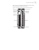
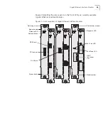
Figure 19 shows the two available Fast Ethernet Interface Modules. Table 11
describes the purpose of the LEDs on each module.
Figure 19 Front Faceplates of Switch 4005 Fast Ethernet Interface Modules
Port Link LED
Ejector handle
RJ-45 ports
Release button
Port Mode LED
Ejector handle
Port Link LED
MT-RJ ports
Model number
Diagnostic LED
Retaining screw
Slot number window
Port Mode LED
Release LED
Содержание 4005
Страница 28: ...28 CHAPTER 4 SWITCH 4005 CHASSIS ...
Страница 36: ...36 CHAPTER 5 SWITCH 4005 POWER SUPPLIES ...
Страница 76: ...76 GLOSSARY ...


