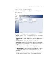

Defining RADIUS Authentication
49
■
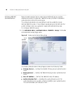
Number of Retries
— Defines the number of transmitted requests
sent to the RADIUS server before a failure occurs. Possible field values
are 1-10. The default value is 3.
■
Timeout for Reply
— Defines the amount of time (in seconds) the
device waits for an answer from the RADIUS server before retrying the
query, or switching to the next server. Possible field values are 1-30.
The default value is 3.
■
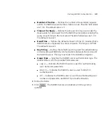
Dead Time
— Defines the default amount of time (in minutes) that a
RADIUS server is bypassed for service requests. The range is 0-2000.
The default value is 0.
■
Key String
— Defines the default key string used for authenticating
and encrypting all RADIUS-communications between the device and
the RADIUS server. This key must match the RADIUS encryption.
■
Usage Type
— Specifies the RADIUS server authentication type. The
default value is
All
. The possible field values are:
■
Log in —
Indicates the RADIUS server is used for authenticating
user name and passwords.
■
802.1X
— Indicates the RADIUS server is used for 802.1X
authentication.
■
All
— Indicates the RADIUS server is used for authenticating user
names and passwords, and 802.1X port authentication.
2
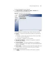
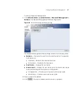
Define the fields.
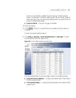
3
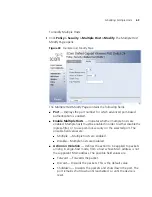
Click
. The RADIUS Servers are enabled, and the system is
updated.
Содержание 3CRUS2475 24
Страница 137: ...Defining LAG Membership 137...
Страница 139: ...139 Defining Voice VLAN Defining GVRP...
Страница 194: ...194 CHAPTER 9 CONFIGURING IP INFORMATION Static Indicates the ARP entry is a static entry...
Страница 197: ...Defining ARP Interface Settings 197 Unchecked Maintains the current ARP entries...
Страница 286: ...286 CHAPTER 15 VIEWING STATISTICS 3 Click The RMON Events are defined and the device is updated...
Страница 321: ...320 APPENDIX C TROUBLESHOOTING...
Страница 329: ...328 APPENDIX GLOSSARY...