background image

Spanning Tree Protocol

5-15

An Example

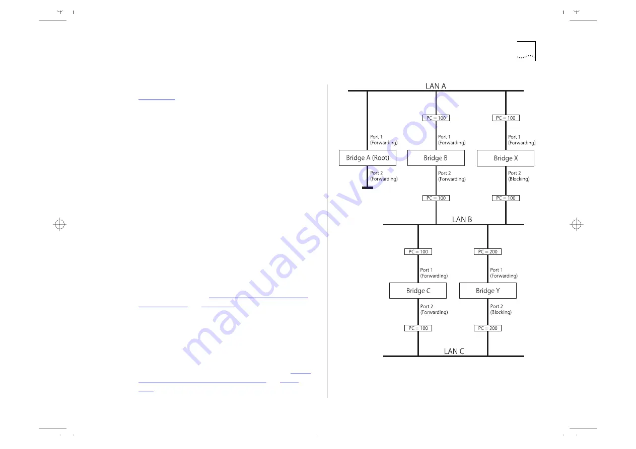
Figure 5-13

 illustrates part of a network. All bridges 

have a path cost value assigned to each port, identi-
fied by PC=xxx (where xxx is the value). 

Bridge A is selected by STP as the Root Bridge, 
because it has the lowest Bridge Identifier. The Des-
ignated Bridge Port for LAN A is port 1 on Bridge A. 
Each of the other four bridges have a Root Port (the 
port closest to the Root Bridge). Bridge X and Bridge 
B can offer the same path cost to LAN B. In this 
case Bridge B's port is chosen as the Designated 
Bridge Port, because it has the lowest Bridge Identi-
fier. Bridge C's port is chosen as the Designated 
Bridge Port for LAN C because it offers the lowest 
Root Path Cost (the route through Bridge C and B 
costs 200, the route through Bridge Y and B would 
cost 300). You can set the path cost of a bridge 
port to influence the configuration of a network 
with a duplicate path. 

Once the network topology is stable, all the bridges 
listen for special Hello BPDUs transmitted from the 
Root Bridge at regular intervals. If the STP Max Age 
time expires (refer to 

“Configuring the STP Parame-

ters of VLANs”

 on 

page 5-18

) before receiving a 

Hello BPDU, it assumes that the Root Bridge, or a 
link between itself and the Root Bridge, has gone 
down. It then initiates a reconfiguration of the net-
work topology.

You can adjust timers to determine how quickly a 
network reconfigures and therefore how rapidly the 
network recovers from a path failure (refer to 

“Con-

figuring the STP Parameters of VLANs”

 on 

page 

5-18

).

Figure 5-13   

Port costs in a network

Содержание 1000

Страница 1: ...http www 3com com SuperStack II Switch 1000 User Guide Agent Software Version 3 1 Document No DUA1690 0AAA05 Published June 1997...

Страница 2: ...ect to restrictions set forth in subparagraph a through d of the Commercial Computer Software Restricted Rights Clause at 48 C F R 52 227 19 and the limitations set forth in 3Com Corporation s standar...

Страница 3: ...ng Tree Protocol 1 5 PACE 1 6 Switch 1000 on Your Network 1 6 Server Connections 1 6 Network Configuration Examples 1 6 Network Segmentation I 1 7 Network Segmentation II 1 8 Desktop Switching 1 9 Uni...

Страница 4: ...Logging On 3 7 After Logging On 3 8 Switch Management Setup 3 9 Logging Off 3 12 Auto Logout 3 12 4 MANAGING THE SWITCH 1000 Setting Up Users 4 2 Creating a New User 4 3 Deleting a User 4 4 Editing U...

Страница 5: ...ing AutoSelect VLAN Mode 5 11 Spanning Tree Protocol 5 12 What is STP 5 12 How STP Works 5 14 STP Initialization 5 14 STP Stabilization 5 14 STP Reconfiguration 5 14 An Example 5 15 STP Configurations...

Страница 6: ...8 Glasfaser Anschlu en A 8 B SCREEN ACCESS RIGHTS C TROUBLE SHOOTING LEDs C 1 Using the VT100 Interface C 2 Using the Switch C 3 D PIN OUTS Null Modem Cable D 1 PC AT Serial Cable D 1 Modem Cable D 2...

Страница 7: ...m the information in this guide follow the Release Notes Throughout this guide the SuperStack II Switch 1000 is referred to as the Switch 1000 or Switch How to Use This Guide This table shows where to...

Страница 8: ...guide you must type something and then press the Return or Enter key Do not press the Return or Enter key when an instruction simply says type Key names Key names appear in text in one of two ways Ref...

Страница 9: ...sfer Mode ATM and Fast Ethernet Transceiver Module slot 10Mbps Ethernet Support for up to 500 endstations unlimited sta tions on backbone port Four forwarding modes for packets Intelligent Flow Manage...

Страница 10: ...ould be used for example to provide a Fast Ethernet or Asynchronous Transfer Mode ATM backbone connection to the rest of your network Transceiver Module A slot at the rear of the unit allows you to in...

Страница 11: ...ag ment Free Store and forward or Intelligent Operation when packet buffers full Discard packets Invoke Intelligent Flow Management to suppress transmis sions at source Spanning Tree Supported Optiona...

Страница 12: ...n 18 errors a second it operates in Fast Forward mode If the Switch detects 18 or more errors a second it operates in Store and Forward mode until the number of errors a second returns to zero For mor...

Страница 13: ...formation about resilient links refer to Setting Up Resilient Links on page 4 19 Virtual LANs The Switch 1000 has a Virtual LAN VLAN feature which allows you to build your network segments without bei...

Страница 14: ...ncreasing the quality of the traffic For more information about setting up PACE on the Switch refer to Setting Up the Switch Unit and Setting Up the Switch Ports in Chapter 4 Switch 1000 on Your Netwo...

Страница 15: ...n I This example shows how the Switch 1000 fits into a large corporate network with a Fast Ethernet infrastructure A Switch is positioned on each floor and servers are centralized in the basement Figu...

Страница 16: ...ample shows the Switch 1000 in a second workgroup situation This setup could be that of a small office within a large corporation or part of a larger corporate network Most of the switch ports have mu...

Страница 17: ...tch 1000 used for a group of heavy traffic users in a large corporate network Here switching is brought to the desktop with a single endstation per switch port A local server is connected using the 10...

Страница 18: ...1 10 CHAPTER 1 GETTING STARTED Unit Overview Front Figure 1 4 Switch 1000 front view 3C16901A top 3C16900A bottom...

Страница 19: ...EDs on page C 1 LED Color Indicates TCVR Yellow Port 1 is a Transceiver Module fitted to the rear of the unit Port Status LEDs Packet Yellow Frames are being transmitted received on the port Status Gr...

Страница 20: ...1 12 CHAPTER 1 GETTING STARTED Unit Overview Rear Figure 1 5 Switch 1000 rear view...

Страница 21: ...y out remote or local out of band configuration and man agement The console port is set to auto baud 8 data bits no parity and 1 stop bit Plug in Module Slot Use this slot to install a Plug in Module...

Страница 22: ...acility can manage the unit if the Management Information Base MIB is installed correctly in the management workstation The Switch 1000 supports SNMP over both IP and IPX protocols Port Status Enabled...

Страница 23: ...onnecting a VT100 Termi nal on page 2 7 The terminal should be config ured to 9600 line speed baud rate 8 data bits no parity and 1 stop bit 2 Press Return one or more times until the Main Banner scre...

Страница 24: ...1 16 CHAPTER 1 GETTING STARTED...

Страница 25: ...taining two mounting brack ets and six screws is supplied with the Switch When deciding where to position the unit ensure that You are able to meet the configuration rules detailed in the following se...

Страница 26: ...ter topologies one hub stack per wiring closet with a fiber run to the collapsed backbone For example a 225m 738ft fiber downlink from a repeater to a router or switch plus 100m 328ft UTP run from a r...

Страница 27: ...Configuration Rules with Full Duplex 2 3 Figure 2 1 Fast Ethernet configuration rules...

Страница 28: ...ten with a suit able screwdriver 4 Repeat steps 2 and 3 for the other side of the unit 5 Insert the unit into the 19 inch rack and secure with suitable screws not provided Ensure that ventila tion hol...

Страница 29: ...th a suitable screwdriver 4 Repeat for the other side of the unit 5 Ensure that the wall you are going to use is smooth flat dry and sturdy Attach a piece of plywood approximately 305mm x 510mm x 12mm...

Страница 30: ...to LEDs on page 1 11 Connecting a Redundant Power System RPS You can connect a SuperStack II Redundant Power System RPS to the Switch At 5V the current requirement for the Switch is 4 8A including an...

Страница 31: ...Terminal To connect a VT100 terminal directly to the console port on the Switch you need a standard null modem cable 1 Connect one end of the cable to the console port on the Switch and the other to t...

Страница 32: ...Cables required for this connection depend on the type of workstation you are using You must config ure the workstation to run SLIP Refer to the docu mentation supplied with the workstation for more...

Страница 33: ...user sessions concurrently for example one console port and three Telnet connections You can establish VT100 management communica tion with the Switch through two different inter faces Via the Console...

Страница 34: ...n Managing Over The Network Any Network Manager running the Simple Network Management Protocol SNMP can manage the Switch provided the MIB Management Informa tion Base is installed correctly on the ma...

Страница 35: ...you do not have a registered IP address you may be using an identical address to someone else and your network will not operate correctly Obtaining a Registered IP Address InterNIC Registration Servi...

Страница 36: ...u wish to replace the default simply enter a new value for this field the default entry is erased Press Down Arrow or Return to move to the next field Button OK Text for a button is always shown in up...

Страница 37: ...racter in an editable field Ctrl R refreshes the screen Ctrl B moves the cursor to the next button Ctrl P aborts the current screen and returns you to the previous screen Ctrl N actions the inputs for...

Страница 38: ...any fur ther configuration If you are using the IPX protocol the Switch is allocated an IPX address automatically You can start the SNMP Network Manager and begin managing the Switch If you are using...

Страница 39: ...ts The defaults are shown in Table 3 1 If you are setting up the Switch for management we suggest that you log on first as admin Figure 3 2 Logon screen Table 3 1 Default Users User Name Default Passw...

Страница 40: ...ss to options depends on the access level you have been assigned Access rights to the VT100 screens for the Switch are listed in Appendix B If you are a user with security access level and are using t...

Страница 41: ...determine the type of self test that the Switch carries out when it is powered up If the field is set to Normal the Switch performs a Fast Boot a basic confidence check lasting approximately 13 second...

Страница 42: ...ddress is automatically mapped to the Switch when it is first powered up In addition to mapping an IP address BOOTP can also assign the subnet mask and default router Using a BOOTP server avoids havin...

Страница 43: ...n to display the setup screen for trap parameters Trap setup is described in Setting Up Traps on page 4 24 CONSOLE PORT Select this button to display the setup screen for console port parameters Conso...

Страница 44: ...eys for 3 min utes the management facility warns you that the inactivity timer is about to expire If you do not press a key within 10 seconds the timer expires and the screen is locked any displayed s...

Страница 45: ...or the Switch 1000 While following steps in these chapters you may find the screen map below useful Figure 4 1 Screen map If an ATM OC 3c Module is installed in the Switch extra screens are available...

Страница 46: ...ou to set up access levels for users on the Switch CREATE USER screen This allows you to create up to 10 users in addition to the default users set up on the Switch DELETE USERS screen This allows you...

Страница 47: ...n Access Level Assign an access level for this new user as follows monitor access to view but not change a subset of the manageable parameters of the Switch secure monitor as monitor manager access to...

Страница 48: ...is displayed 1 Select the DELETE USERS option The Delete Users screen is displayed as shown in Figure 4 4 2 Use the spacebar to highlight the user that you want to delete Note that you cannot delete...

Страница 49: ...be changed if you need to change the user name you must delete this user and create a new one Old Password To change the user s password enter the current password in this field New Password This fiel...

Страница 50: ...onsole port disable access to the facility for each access level Console port access for Security is enabled and cannot be changed This prevents accidental dis abling of all access levels from managem...

Страница 51: ...e screen relate to an individual port If you choose Unit the screen appears similar to Figure 4 8 and all options relate to the Switch unit If you choose VLAN the screen appears similar to Figure 4 9...

Страница 52: ...anagement you have chosen port or unit Refer to Chapter 6 SDB Use this button to display the Unit Database View screen which is used to manage the Switch Database Refer to The Database View on page 4...

Страница 53: ...d onto the network Fragment Free A minimum of 512 bits of the received frame is buffered prior to the frame being forwarded This ensures that collision frag ments are not propagated through the networ...

Страница 54: ...peater Also Interac tive Access should only be enabled at one end of the link For more information about disabling Interactive Access for a port refer to Setting Up the Switch Ports on page 4 12 VLAN...

Страница 55: ...Back bone and all the ports on the Switch belong to VLAN 1 and use Port VLAN Mode then this field allows you to specify a backbone port for the Switch In all other situations the field is not dis play...

Страница 56: ...r disable the port To prevent unauthorized access we recommend that you disable any unused ports Link State Present Not Available This read only field shows the state of the link Present The port is o...

Страница 57: ...MP management A more comprehensive set of security features is available through SNMP network management Security is not available on backbone ports If the port has been defined as a backbone port the...

Страница 58: ...t the port is manually placed in the required VLAN AutoSelect The port uses AutoSelect VLAN Mode which means that the port is automatically placed in the required VLAN by referring to a VLAN Server da...

Страница 59: ...vent enable event enable Use this field to specify the action for the alarm to take when it reaches the falling threshold none no action takes place event an SNMP trap is generated enable the port is...

Страница 60: ...efer to the description for the Security field on page 4 13 The system administrator can enter and update entries using a MIB browser an SNMP Network Manager or the Switch Database screen described in...

Страница 61: ...dentifier for the entry Permanent Yes No This field allows you to specify that the current entry is permanent Refer to the previous section Setting Up the Switch Database SDB for a description of perm...

Страница 62: ...C addresses entered against a par ticular port ID in the SDB 1 Clear the MAC Address field by moving into the field and pressing Space 2 In the Port Number field enter the port ID for which you want M...

Страница 63: ...atically switched back to the main link provided no loss of link is detected for two minutes Otherwise you need to manually switch traffic back to the main link When setting up resilient links you sho...

Страница 64: ...ed Not Present The port is not present in the cur rent hardware Standby Port ID This field shows the current standby port ID and allows you to enter a new port ID The standby port must be in the same...

Страница 65: ...u must remove cabling from the ports to avoid creating loops in your network configuration Creating a Resilient Link Pair 1 Ensure that the port nominated as the standby port is not physically connect...

Страница 66: ...of carrying traffic Both Failed Although the resilient link is cor rectly configured both links have failed Check for any loose connections or cable damage Unknown The network configuration has change...

Страница 67: ...ether the resilient link pair is currently enabled or disabled You enable or disable a resilient link pair using the Port Resilience screen described in Configuring Resilient Links on page 4 20 OK Thi...

Страница 68: ...hich traps should be sent Community String This field allows you to enter community strings for each remote Network Man ager allowing a very simple method of authentica tion between the Switch and the...

Страница 69: ...Local DCD Control Enabled Disabled This field is only applicable to local connection types It determines if DCD is required for a local connection and whether the connection is closed if DCD is remov...

Страница 70: ...d is set automatically Char Size 8 This read only field shows the character bit data bit size for the Switch You should set your terminal to the same value Parity NONE This read only field shows the p...

Страница 71: ...u select the RESET option The Reset screen is displayed as shown in Figure 4 18 2 Select OK Resetting the Switch in this way is similar to per forming a power off on cycle No setup information is lost...

Страница 72: ...cleared from memory and cannot be recovered After initialization all user information is lost and only default users are available All ports are set to their default values and are therefore enabled a...

Страница 73: ...The download does not work over an ATM link If a software download over IPX fails enter the MAC or Ethernet address of your server into the Switch Database via the Unit Database View screen and then...

Страница 74: ...4 30 CHAPTER 4 MANAGING THE SWITCH 1000 5 Select OK During the download the MGMT LED flashes green and the screen is locked When the download is complete the Switch is reset...

Страница 75: ...physically connects them the segments are defined by flexible user groups that you create using software With VLANs you can define your network according to Departmental groups For example you can ha...

Страница 76: ...e efficiency of your network because each VLAN can be set up to contain only those devices which need to communicate with each other How VLANs Provide Extra Security Devices within each VLAN can only...

Страница 77: ...can only take place if they are all connected to the router A VLAN not connected to a router is an isolated VLAN You need one port for each VLAN connected to the router Connecting Common VLANs Between...

Страница 78: ...he VLAN AutoSelect VLAN Mode has an advantage over Port VLAN Mode because once the VLAN Server data base is set up correctly you can move endstations to other ports or other Switch units and the VLAN...

Страница 79: ...ATM OC 3c Module installed you can extend the VLANs you have defined in your existing network into an ATM network For more information refer to the SuperStack II Switch ATM OC 3c Module User Guide VL...

Страница 80: ...ect port 26 of the higher Switch to Server 1 3 Connect port 26 of the lower Switch to Server 2 4 Use the VT100 screens or VLAN Server database to a Place port 26 of the higher Switch in VLAN 2 b Place...

Страница 81: ...100 screens to a Specify that each Switch 1000 port connected to the Switch 3000 FX is a backbone port b Specify that each Switch 1000 port connected to the Switch 3000 FX is a VLT port c Specify that...

Страница 82: ...A Virtual LAN Trunk or VLT is a Switch to Switch link which carries traffic for all the VLANs on each Switch For more information about VLTs in general refer to VLANs and the Switch on page 5 3 To sp...

Страница 83: ...Backbone Port Yes No If the port specified in the Port ID field uses Port VLAN Mode this field allows you to specify whether the port is a backbone port If the port uses AutoSelect VLAN Mode or is th...

Страница 84: ...ager to access the management agent of the unit If you remove all ports from VLAN 1 then an SNMP Network Manager cannot manage the Switch Specifying a Backbone Port 1 In the Port ID field type the ID...

Страница 85: ...ckup VLAN Server A backup VLAN Server can be used to supply VLAN allocations when the Switch cannot access the main VLAN Server VLAN Server Community String This field allows you to enter a community...

Страница 86: ...aths for network traffic and ensure that Redundant paths are disabled when the main paths are operational Redundant paths are enabled if the main paths fail As an example Figure 5 10 shows a network c...

Страница 87: ...Spanning Tree Protocol 5 13 Figure 5 10 A network configuration that creates loops Figure 5 11 Traffic flowing through Bridges C and A Figure 5 12 Traffic flowing through Bridge B...

Страница 88: ...gment has one Designated Bridge Port All traffic destined to pass in the direction of or through the Root Bridge flows through this port The Designated Bridge Port is the port which has the lowest Roo...

Страница 89: ...the lowest Root Path Cost the route through Bridge C and B costs 200 the route through Bridge Y and B would cost 300 You can set the path cost of a bridge port to influence the configuration of a netw...

Страница 90: ...rs a duplicate path and disables one of the links If the enabled link breaks the disabled link becomes re enabled therefore maintaining con nectivity Configuration 2 Redundancy through Meshed Backbone...

Страница 91: ...OK You cannot enable STP if you have set up resilient links on any of the Switch ports or if you are using VLAN 16 CAUTION If STP is enabled on your Switch 1000 and the Switch is connected to another...

Страница 92: ...ield allows you to specify the VLAN to be configured If you are using STP you cannot use VLAN 16 Also if you are using AutoSelect VLAN Mode you cannot use VLAN 15 In these cases the relevant VLANs are...

Страница 93: ...ange the priority of the Switch unless absolutely necessary Bridge Max Age 6 40 This field allows you to specify the time in seconds that the Switch waits before trying to re configure the network whe...

Страница 94: ...does not forward packets and does not participate in STP opera tion Listening A port in this state is preparing to forward packets but has temporarily blocked to prevent a loop During the Listening st...

Страница 95: ...ority of the port you can make it more or less likely to become the Root Port The lower the number the more likely it is that the port will be the Root Port The default setting for this field is 128 P...

Страница 96: ...abbreviation for the Remote Monitoring MIB Management Information Base a system defined by the IETF documents RFC 1271 and RFC 1757 which allows you to monitor LANs remotely A typical RMON setup consi...

Страница 97: ...ms group provides a versatile general mechanism for setting thresholds and sampling intervals to generate events on any RMON variable Both rising and falling thresholds are supported and thresholds ca...

Страница 98: ...hat match a specific criterion or condition Capture The Capture group allows you to create capture buffers on the probe that can be requested and uploaded to the management workstation for decoding an...

Страница 99: ...on before problems occur This means that you can take action before they impact on users In addition probes record the behavior of your network so that you can analyze the causes of problems How RMON...

Страница 100: ...to be attached to a non secure port Implementing RMON in the Switch means all ports can have security features enabled RMON Features of the Switch Table 5 2 details the RMON support provided by the Sw...

Страница 101: ...a Hosts session is started on the Default VLAN for more information refer to Setting Up the Switch Unit on page 4 9 Hosts Top N Although Hosts Top N is supported by the Switch there are no Hosts Top...

Страница 102: ...t on Blip port Block broadcast and multi cast traffic on the port for 5 seconds Disable port Turn port off Enable port Turn port on Notify and move resilient port Send Trap If port is the main port of...

Страница 103: ...SNMP Network Manager Each entry in the log contains information in the fol lowing order Entry number Timestamp User ID Item ID including qualifier New value of item There is a limit of 16 records on t...

Страница 104: ...5 30 CHAPTER 5 ADVANCED MANAGEMENT...

Страница 105: ...for the Switch 1000 and advises you on actions to take if you see unexpected values for the statistics Please note however that as all networks are different any actions listed are only recommendation...

Страница 106: ...MITTED Displays values for the Frame Transmitted counter the total number of frames successfully transmitted by the current port including fragments and frames with errors FRAMES FORWARDED Displays th...

Страница 107: ...station segments is an indica tion that your network is operating efficiently However if multiple endstations are connected to this port and you see values of around 40 you should reconsider the topol...

Страница 108: ...et boundary Octets Transmitted The number of octets transmit ted by the port The calculation includes the MAC header and CRC but excludes preamble SFD Octet counters are accurate to the nearest 256 oc...

Страница 109: ...value shown should be a very small proportion of the total data traffic IFM Count The number of times Intelligent Flow Management IFM has had to operate to minimize packet loss Frame Size Analysis The...

Страница 110: ...Events This counter is incremented by one for each carrier event whose duration is less than the short event maximum time Short events are error frames smaller than the minimum size defined for Ethern...

Страница 111: ...but including FCS octets CLEAR SCREEN COUNTERS Select this button to set all counters shown on the screen to zero It is useful for trend analysis if you wish to see changes in counters over a short pe...

Страница 112: ...as first installed or initial ized either power on manual reset or a watchdog expiry Last Reset Type Other Command Watchdog Power reset System error This field indicates the cause of the last reset It...

Страница 113: ...n The Fault Log screen is displayed as shown in Figure 6 6 The Fault Log screen shows the following Reset Count The number of resets recorded at the time of the fault Time seconds The time elapsed sin...

Страница 114: ...a device 1 From the Main Menu select Remote Poll The Remote Poll screen is displayed as shown in Figure 6 7 2 In the Target Address field enter the IP or IPX address of the device you want to poll 3...

Страница 115: ...t must be earthed Connect the unit to an earthed power supply to ensure compliance with European safety stan dards The power cord set must be approved for the country where it will be used The applian...

Страница 116: ...nt to which it is connected is also opera tional under SELV The unit should never be connected to an A C outlet power supply without an Earth Ground connection To comply with European safety standards...

Страница 117: ...ect a 3Com Redundant Power System to this socket For details follow the installation instructions in the manuals accompanying the Redundant Power System RJ45 Ports The RJ45 ports are shielded RJ45 dat...

Страница 118: ...admission d appareil EN60320 IEC320 Pour USA et le Canada Le cordon surmoul doit tre UL Certifi et CSA Certifi Les sp cifications minimales pour le cordon souple sont No 18 AWG Type 5V ou SJ 3 conduc...

Страница 119: ...ltation de module d metteur r cepteur avec la puissance encore branch e La Source de Courant et Le Fusible L unit s ajuste automatiquement la tension d ali mentation Le fusible est convenable aux deux...

Страница 120: ...ou non blind s l un ou l autre peuvent tre branch s ces prises de courant de donn es Les Ports Fibre Sous les conditions de visionnement ordinaires il n y a pas de danger l oeil cause de la diode lec...

Страница 121: ...Wandstecker mu in den EN60320 IEC320 Zuf hrungsstecker am Ger t passen Es ist wichtig da der Netzstecker sich in unmit telbarer N he zum Ger t befindet und leicht erre ichbar ist Das Ger t kann nur du...

Страница 122: ...System an diese Steckdose anschlie en F r weitere Angaben die genauen Einbauanweisungen im Handbuch zum Redundant Power System befolgen RJ45 Anschlu en Hierbei handelt es sich um abgeschirmte RJ45 Dat...

Страница 123: ...ity Switch Management Monitor Manager Security Port STP Monitor read only Manager Security Port Statistics Monitor Manager Security Port Traffic Statistics Monitor Manager Security Port Error Analysis...

Страница 124: ...ty Create User Security Delete Users Security Edit User Monitor Manager Security Status Monitor Manager Security Fault Log Monitor Manager Security Management Setup Monitor read only Manager Security...

Страница 125: ...g the Plug in Module ensuring it is properly seated If the prob lem persists contact your supplier for advice The Plug in Module Status LED lights yellow If the MGMT LED is flashing yellow the Module...

Страница 126: ...efault router are correctly configured and that the device has been reset Check that the device s IP address is correctly recorded by the SNMP Network Manager refer to the user documentation for the N...

Страница 127: ...supplier Using the Switch You see network problems and the Packet LED is on continuously with constant collisions viewed using the Port Traffic Statistics screen refer to Port Traffic Statistics on p...

Страница 128: ...refer to Configuring the STP Parameters of Ports on page 5 20 2 Specify that the endstation entries are Non ageing refer to Setting Up the Switch Database SDB on page 4 16 3 If the network has less t...

Страница 129: ...ommend that you connect the two SuperStack II Switch units using a Virtual LAN Trunk VLT For more information about VLTs refer to Connecting Common VLANs Between Switch Units on page 5 3 Figure C 1 Ne...

Страница 130: ...C 6 APPENDIX C TROUBLE SHOOTING...

Страница 131: ...D PIN OUTS Null Modem Cable 9 pin to RS 232 25 pin PC AT Serial Cable 9 pin to 9 pin...

Страница 132: ...D 2 APPENDIX D PIN OUTS Modem Cable 9 pin to RS 232 25 pin RJ45 Pin Assignments Pin assignments are identical for 10BASE T and 100BASE TX RJ45 connectors...

Страница 133: ...Delay Fuse Electromagnetic Compatibility EN55022 Class B FCC Part 15 Subpart B Class A ICES 003 Class A VCCI Class 2 AS NZS 3548 Class B EN 50082 1 Category 5 screened cables must be used to ensure c...

Страница 134: ...protocol RFC 1157 MIB II RFC 1213 Bridge MIB RFC 1493 Repeater MIB RFC 1516 VLAN MIB RFC 1573 RMON MIB RFC 1271 and RFC 1757 Terminal Emulation Telnet RFC 854 Protocols Used for Administration UDP RF...

Страница 135: ...features news and information about 3Com products customer service and support 3Com Corporation s latest news releases NetAge Magazine technical documentation and more 3Com Bulletin Board Service 3Com...

Страница 136: ...tches software drivers and technical articles about all 3Com products as well as a messaging section for peer support To use 3ComForum you need a CompuServe account To use 3ComForum 1 Log on to your C...

Страница 137: ...re available from 3Com Contact your local 3Com sales office to find your authorized service provider using one of these numbers Regional Sales Office Telephone Number 3Com Corporation U S 3Com ANZA Ea...

Страница 138: ...Italy 3Com Middle East 3Com Nordic AB Denmark Finland Norway Sweden 3Com Russia 3Com South Africa 3Com U K Limited 54 1 312 3266 55 11 546 0869 56 2 633 9242 57 1 629 4110 52 5 520 7841 51 1 221 5399...

Страница 139: ...network used as the primary path for transporting traffic between network segments backbone port A port which does not learn device addresses and which receives all frames with an unknown address Back...

Страница 140: ...wo devices transmit simultaneously a collision occurs and the colliding devices delay their retransmissions for a random amount of time data center switching The point of aggregation within a corporat...

Страница 141: ...ination port line speed See baud rate main port The port in a resilient link that carries data traffic in normal operating conditions MDI MDIX Medium Dependent Interface A type of Ethernet twisted pai...

Страница 142: ...protocol which allows IP to run over a serial line connection SmartAgent Intelligent management agents in devices and logi cal connectivity systems that reduce the computa tional load on the network...

Страница 143: ...ser were connected directly to the host TFTP Trivial File Transfer Protocol Allows you to transfer files such as software upgrades from a remote device using your Switch s local management capa biliti...

Страница 144: ...6 GLOSSARY...

Страница 145: ...imum length 1 11 2 2 pin outs D 1 Capture RMON group 5 24 Char Size field 4 26 Community String field 4 3 4 5 4 24 community strings changing 4 5 role in trap setup 4 24 Community SNMP field 4 6 Compu...

Страница 146: ...Bridge Max Age 5 19 Bridge Priority 5 19 Bridging Mode 4 10 Broadcast Storm Control 4 14 Char Size 4 26 Community String 4 3 4 5 4 24 Community SNMP 4 6 Confirm Password 4 5 Connection Type 4 25 Conso...

Страница 147: ...lligent Forwarding field 4 9 Intelligent Switching Mode 1 4 Interactive Access disabling 4 13 IP address default router 3 10 device 3 10 entering 1 15 format 3 2 IP or IPX Address field 4 24 IP protoc...

Страница 148: ...7 resilient link pair 4 19 resilient links 1 5 configuring 4 20 creating 4 21 deleting 4 21 rules 4 19 setting up 4 19 viewing 4 22 returning products for repair F 4 Rising Action field 4 15 Rising Th...

Страница 149: ...g on 3 7 management setup 3 9 port setup 4 12 positioning 2 1 powering up 2 6 rack mounting 2 4 rear view 1 12 resetting 4 27 size E 1 stacking with other units 2 4 unit defaults 1 14 unit setup 4 9 u...

Страница 150: ...dress field 5 11 VLAN Server screen 5 11 VLAN Setup screen 5 8 VLAN STP screen 5 18 VLANs 1 5 5 1 assigning ports 5 10 AutoSelect VLAN Mode 5 3 Default 5 3 5 9 extending into an ATM network 5 5 Port V...

Страница 151: ...thin the warranty period Products returned to 3Com s Corporate Service Center must be pre authorized by 3Com with a Return Material Authorization RMA number marked on the outside of the package and se...

Страница 152: ...eption which can be determined by turning the equipment off and on the user is encouraged to try to correct the interference by one or more of the following measures Reorient the receiving antenna Rel...

Отзывы: