


TC-SPLIT USER MANUAL
5
3C Concept S.A.S
5
TC-SPLIT_MANUEL_EN_105.DOCX
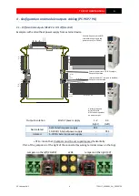
3.3
–
Unipolar encoder (open collector or unipolar TTL/HTL outputs), not isolated
A
B
Z
A
Z
B
0
V
_
EX
T
+V
_
EX
T
1
A
B
Z
A
Z
B
0
V
_E
X
T
+
V
_E
X
T
1
A
B
Z
A
Z
B
0V_EXT
+V_EXT
1
A
B
Z
A
Z
B
0
V
_
EX
T
+
V
_E
X
T
1
A
B
Z
A
Z
B
0
V
_
EX
T
+
V
_E
X
T
1
+
1
0
/3
0
V
1
0
V
SL
A
V
E
Jumper pos. for powering
encoder with 5Vdc
Jumper pos. for powering
encoder with 24Vdc
Encoder or signals
source
Encoder ouput level: 5V/TTL
switch in low pos. (ON)
Encoder ouput level: 10-30Vdc
switch in high pos.(OFF)
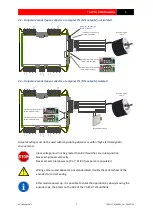
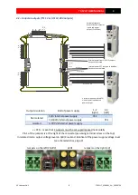
3.4
–
Unipolar encoder (open collector or unipolar TTL/HTL outputs), isolated
A
B
Z
A
Z
B
0
V
_
EX
T
+V
_
EX
T
1
A
B
Z
A
Z
B
0
V
_E
X
T
+
V
_E
X
T
1
A
B
Z
A
Z
B
0V_EXT
+V_EXT
1
A
B
Z
A
Z
B
0
V
_
EX
T
+
V
_E
X
T
1
A
B
Z
A
Z
B
0
V
_
EX
T
+
V
_E
X
T
1
+
1
0
/3
0
V
1
0
V
SL
A
V
E
Encoder or signals
source
Encoder ouput level: 5V/TTL
switch in low pos. (ON)
Encoder ouput level: 10-30Vdc
switch in high pos.(OFF)
+V
Encoder power supply
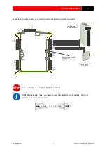
Unipolar wiring must not be used with long cabling distance or within high electromagnetic
environments.
Input voltage must not be greater than 8V if switches are in low position
Never set jumpers vertically
Never set external power on [P1.7; P1.8] if jumpers are populated
Wiring colours used above are not standardized, double check datasheet of the
encoder for correct wiring
After module power up, it is possible to check the operation by slowly moving the
encoder axis, the 3 leds on the side of the TC-SPLIT should blink.


