background image

Chapter 4. AVALON H SETUP

4-11 


OZP

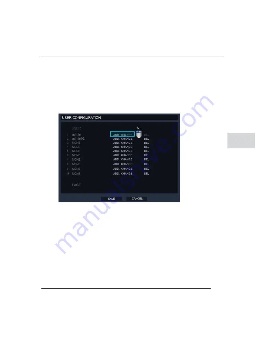
 User configuration 

In user configuration, you can add, delete and change each user’s permission or login 
authorization.  


To add a new user 


1.Click on the ‘ADD/CHANGE’ 

͑


͑


2.Enter the username and password for the new account. 


3.Set the user’s permission, these are the DVR functions they will be able to operate. 

4.Then click the ‘OK’ button to create the account. 


Содержание AVALON H 5004

Страница 1: ...G G G G G G G G G G G G G G G G G G G G G G G G G G G G G G G G 8KUKQP 6GEJPQNQI AVALON H User Manual ...

Страница 2: ...AVALON H Gt G G G ...

Страница 3: ...ordance with copyright policy AVALON H 5004 5008 5016 is 360 Vision Technology s trade mark The logo of the AVALON H series and that of Avalon is a trademark of 360 Vision Technology Company limited Ethernet is a trade mark of Xerox Corporation Microsoft MS DOS the Windows logo Windows and Windows NT used in the USA and other countries is a trade mark of Microsoft Corporation x The manufacturer im...

Страница 4: ...AVALON H User Manual ii ...

Страница 5: ...fety information they must be fully complied with Danger Risk of death or serious injury This is the highest priority danger warning Warning Risk of serious or lesser degree of injury May also cause damage to the product or to property Caution Risk of minor injury or damage Important Requirements or limitations regarding operation Users are recommended to read the relevant details carefully so as ...

Страница 6: ...ay result in fire and electric shock Do not place containers with liquid or small metal objects on top of the product Liquid or small metal objects getting into the unit may lead to fire and electric shock Please connect the power cord only to the type of AC outlet indicated in the manual or product specification If connected to other types of power outlet fire and electric shock may result Do not...

Страница 7: ...in electric shock Please use only the correct voltage with the product Use of incorrect power voltage may result in fire and electric shock If the product is dropped or damaged turn off the power switch and remove the power cord from the power outlet Continued operation of the product may result in fire and electric shock In case of smoke or burning odor immediately turn off the power switch and r...

Страница 8: ...beverages may result in damage that cannot be repaired Excessive current from the product and the camera may result in an electric shock Connect the power cord to an external device only when the products themselves are disconnected from their power supply ΈΒΣΟΚΟΘ Non compliance may result in a serious or lesser degree of injury It may also cause damage to the product or to property ...

Страница 9: ...the product If this product is damaged beyond repair or reaches its maximum service life dispose of it in compliance with local laws and regulations regarding the disposal of lead and plastic waste Do not operate or store the product in the following places An area that is either too cold or too hot An area of high humidity or in front of an air conditioner or in places subject to sudden temperatu...

Страница 10: ...here is a risk of malfunction from external causes Ensure periodic maintenance by the certified installers The product may not work properly if the power source is unstable or and if electric shock occurs Make sure the correct rated power is available The product is designed to be proof against electric power failures however damage may occur as a result of power failure Current data may be damage...

Страница 11: ...t AVALON H 1 3 2 AVALON H Specification 1 4 3 System Diagram 1 5 4 Components 1 6 Chapter 2 Start AVALON H 2 1 1 AVALON H Outlook 2 3 1 Front Design 2 3 2 Rear panel and connection locations 2 10 3 Remote controller 2 12 2 How to Install 2 14 1 Installation 2 14 2 Replace CMOS battery 2 20 Chapter 3 Operating AVALON H 3 1 1 Log In 3 3 2 Live Mode 3 4 1 Select a Channel 3 4 2 Icon 3 5 3 Pop Up Menu...

Страница 12: ...1 1 Setup Menu 4 3 1 About Setup 4 3 2 System Setup 4 4 1 System configuration 4 5 2 Disk Configuration 4 10 3 User configuration 4 11 4 Configuration 4 13 5 Shutdown 4 13 3 Camera 4 14 1 Camera Configuration 4 14 2 PTZ Configuration 4 15 3 Spot Sequence configuration 4 16 4 Monitor Configuration 4 17 4 Record 4 18 1 Record Configuration 4 18 2 Motion Event configuration 4 25 5 Network 4 29 1 Netw...

Страница 13: ...status 4 34 3 Version 4 36 7 Quick Setup 4 37 8 Backup 4 39 1 Backup 4 39 2 Auto USB backup 4 41 3 Backupviewer 4 42 3 Backupviewer options 4 44 Chapter 5 Troubleshooting Guide and Glossary A 1 Troubleshooting Guide A 3 Glossary A 8 Product Warranty Card ...

Страница 14: ......

Страница 15: ...1 1 Lqwurgxfwlrq ri wkh surgxfw ihdwxuhv dqg frpsrqhqwv uhdg ehiruh xvh 1 DYDORQ K K L Lqwurgxfwlrq This guide based on the model AVALON H5016 ...

Страница 16: ...AVALON H User Manual 1 2 ...

Страница 17: ...valon H5000 series Main Features H 264 codec compression PIP picture in picture mode Multi User level access and control system Professionalized menu functions and configuration Powerful remote network applications Large Storage 3 4 HDD optional and Optical device for backup Advanced User friendly interface Easy upgrade by USB memory Supports all main PTZ protocols Loop out composite Video and Spo...

Страница 18: ...CIF 100fps D1 50fps y NTSC CIF 240fps 2CIF 120fps D1 60fps y PAL CIF 200fps 2CIF 100fps D1 50fps Record Resolution NTSC CIF 352x240 2CIF 704x240 D1 704x480 PAL CIF 352x288 2CIF 704x288 D1 704x576 Compression H 264 Mode Motion detection Sensor Schedule Storage Internal 4 x HDD W DVD 3 x HDD y CD R W DVD R W Optional Audio 4 Channel G 723 1 Compression Mode Multi channel playback Max 16ch Calendar E...

Страница 19: ...Chapter 1 Introduction 1 5 1 3 System Diagram AVALON H can be connected with the following devices For more detail on the connection see each chapter s explanation in the manual ...

Страница 20: ... Following components are included in the box with AVALON H ل 1 AVALON H Main unit טטטטטטטטטט ΖΒ ل 2 DC Adapter טטטטטטטטטט ΖΒ ل 3 AVALON H CD טטטטטטטטטט ΖΒ ل 4 Remote controller טטטטטטטטטט ΖΒ ل 5 User s Guide טטטטטטטטטט ΖΒ ل 6 Loopback Cable optional טטטטטטטטטט ΖΒ ل 7 Rack Mount Kit optional טטטטטטטטטט ΖΒ ...

Страница 21: ... 2 1 Read this chapter before installation It contains mandatory items you should know Start AVALON H 2 ...

Страница 22: ...AVALON H User Manual 2 2 ...

Страница 23: ...en you connect 1 AVALON H outlook 1 Front design The below image shows the front case and indicates each part of the case 1 Channel Number buttons Use these buttons to select a channel or enter a number in the setup menu Channel select in Live Search Enter a password when logging into the DVR 2 DVD RW Backup recorded data on to your DVD RW if installed and playback the recordings with the provided...

Страница 24: ...nect mouse to control DVR unit Can be used to perform a Firmware upgrade Make a backup of recorded data 4 Functional buttons This button changes display mode this are pre defined to turn in the order shown below Turn On Off sequence mode This is single channel rotation as shown below Single display sequence ...

Страница 25: ...LON H 2 5 2 4 split display mode sequences in 4 channel groups as shown below 9 split display mode sequences in 9 channel splits as shown below PIP Picture in Picture mode sequences a single channel within a single screen ...

Страница 26: ...r the search mode Press this button to enter the Backup menu Escape from the current mode or return to live screen 5 Directional buttons 1 In the Live Screen or search modes T Left Right Moves to next or previous channel 2 In Menu T Use the directional buttons to move the cursor around each menu 3 In PTZ mode T Use directional buttons to move the PTZ camera in the desired direction 4 Zoom Focus T ...

Страница 27: ...writing data to the HDDs Network LED T This LED turns on when the system is connected to the network IR Sensor T This LED turns on when the system receives a signal from the remote controller ΣΖΤΤ ΠΟΔΖ ΗΣΒΞΖ ΖΧ ΝΒΪΓΒΔΜ ΣΖΤΤ ΥΨΚΔΖ ΥΠ ͻΦΞΡ ΞΚΟ ΚΟ ΥΙΖ ΣΖΧ ΡΝΒΪΓΒΔΜ ΕΚΣΖΔΥΚΠΟ ΣΖΤΤ ΠΟΔΖ ΗΣΒΞΖ ΝΒΪΓΒΔΜ ΣΖΤΤ ΨΚΔΖ ΥΠ ΛΦΞΡ ΞΚΟ ΚΟ ΥΙΖ ΡΝΒΪΓΒΔΜ ΕΚΣΖΔΥΚΠΟ ...

Страница 28: ...In Live mode T Move cursor backward to delete character PLAY PAUSE Toggle between Playback and pause images ΨΚΥΔΙ ΕΚΣΖΔΥΝΪ ΥΠ ΥΙΖ ΤΖΒΣΔΙ ΞΠΕΖ ΗΣΠΞ ΝΚΧΖ ΤΔΣΖΖΟ FASTFOWARD In Search mode T Move forward from current search position T Each press button accelerate the speed from 1x to 32x STOP Stop the current searching process BACKWARD Move backward from current search position frame by frame FOWARD M...

Страница 29: ...rent search position frame by frame T Counter Clockwise movement Move backward from the current search position frame by frame Shuttle Outer circle T Clockwise movement Searches forward through the recorded images T Counter clockwise movement Searches backwards through the recorded images The more the user turns of the rotation of dial there is an increase search speed from 2x to 32x ...

Страница 30: ...utput to the BNC connector Channels locate in the order 1 to 8 from left to right On the 5016 model the lower column is channels 9 to 16 On the 5008 model the lower column is used as Loop thru ᐯ Video Loop thru output for 5016 This loop thru output port can only be used for 5016 model and is an optional extra to the included accessories ᐰ VGA Monitor Out Connect to the VGA monitor on this port ...

Страница 31: ...ard controller ᐵ USB Connector Use to connect with USB devices like USB External HDD or USB Flash Device ᐶ Network Port Connect LAN cable with a RJ45 connector to use the network Network application allows the user to monitor live search and setup the DVR ᐷ RS485 As a signal Communication port this port is used for PTZ camera control ᐸ SENSOR Connect the sensor signal cables to this input The sens...

Страница 32: ...tion Key Move menu in normal mode PTZ control in PTZ mode ENTER to select FOCUS in FOCUS out ZOOM In ZOOM Out 1 Enter 1 to display channel 1 2 Enter 2 to display channel 2 3 Enter 3 to display channel 3 4 Enter 4 to display channel 4 PRESET LOCK LOGOUT LOGIN Instant Recording Shows system status Display on off OSD Select PTZ mode IRIS mode in PTZ 10 press to enter channels 10 and above ...

Страница 33: ...ey to move menu Enter to select EXIT PLAY PAUSE Fast forward playback Reverse playback Switch to live mode 1 Enter 1 to display channel 1 4 Enter 4 to display channel 4 2 Enter 2 to display channel 2 3 Enter 3 to display channel 3 Display on off OSD ...

Страница 34: ...repare and then connect the Monitor Camera and Power cables See following steps on how to make the installation 1 Pre caution No impacts or heavy loads should be applied on the product Do not attempt to disassemble the unit unless trained by the supplier Check your local power supply information is correct Do not spill liquid or no water on this product 2 Connect cameras Connect camera cable onto ...

Страница 35: ...ct to a monitor VGA Monitor or CCTV Monitor Connect to the VGA port or and the TV OUT Port on rear panel of the product 4 Connection of Audio Devices Connect to the Speaker to Audio OUT and Microphone to the Audio IN use separate amplifiers ...

Страница 36: ...AVALON H User Manual 2 16 Caution z Use shielded audio cable to prevent system damage in the instance of a lighting strike 5 Sensor Other device connection examples ...

Страница 37: ...n b Sensor IN connection For each sensor port used you must connect to the GND port To activate a sensor you normally have to supply a separate power supply unit To get more details see sensor connection diagram on the sensor manufacturer s manual Each sensor can have a different connection according to its connection type c Alarm OUT connection relay output The P is for signal connection and N is...

Страница 38: ...tion For each sensor port used you must connect to the GND port To activate a sensor you normally have to supply a separate power supply unit To get more details see sensor connection diagram on the sensor manufacturer s manual Each sensor can have a different connection according to its connection type c Alarm OUT connection relay output The P is for signal connection and N is for COM connection ...

Страница 39: ...use fatal damage on HDD data and HDD 6 Connecting a HDD When connecting a HDD the user must follow the connection details and diagram below Disconnect the Power cable from the DVR a Remove the top cover To open the cover remove screws on both sides and rear b Unscrew the bolts on HDD Optical casing and remove casing c Place the Optical Drive or HDD as you desired then connect the power and data ca...

Страница 40: ...e the battery to explode The user must seek guidance from the supplier before replacement 2 Replace CMOS battery CMOS battery supplies power to the main board clock when the power is off Specification Voltage 3V Capacity 220mAh Standard load 0 2mA Operation Temp 30o C 60 o C ...

Страница 41: ...3 1 Wklv vhfwlrq frqwdlqv lqirupdwlrq derxw wkh uhfruglqj vhdufklqj sod edfn dqg rwkhu rshudwlqj ihdwxuhv ri wkh GYU1 Rshudwlqj DYDORQ K K ...

Страница 42: ...AVALON H User s guide 3 2 ...

Страница 43: ...ess to the DVR controls until you have logged in To log in select the TOOL button from the task bar and then select USER as in the below picture Ways to Log in Mouse front key Remote controller ways to Log Off Front key remote controller Enter a valid user name and password in the login display area and then click OK ...

Страница 44: ...roller buttons Live display can be changed from 1 4 9 16 PiP displays To change display options press the Live button on front panel The following illustrations are examples of the live display modes Double click the left mouse button to select channel To go back to previous display mode double click left mouse button again 1CH 4CH 9CH 16CH PIP ...

Страница 45: ...gency Recording On Sensor Activating Recording PTZ Control On Continuous Motion Alarm Recording Warning for exceeding temperature Continuous Sensor Activating Recording Sequence mode in operation Motion Detection Sensor Activating Recording Digital zoom mode in operation Emergency Recording Sensor Activated Motion Detected Audio Channel PTZ Camera Move mouse to bottom position on the live screen a...

Страница 46: ... icon Playback Function ሪ Click this button to start playback the of the latest recorded data immediately Hold the Task Bar Function If the pin icon has been pressed task bar menu stays displayed regardless of the position of the mouse pointer If not pressed task bar menu will disappeared once the mouse pointer is not over its position 6 Pop up Menu Tip ͿΠ ΚΔΠΟΤ ΚΟ ΥΙΖ ΝΚΧΖ ΤΔΣΖΖΟ ΞΖΒΟΤ ΥΙΖΣΖ ΚΤ Ο...

Страница 47: ...d on bottom of left This function only works when in single channel view not split screens FREEZE ALL This will freeze the live display SHOW MOTION AREA This will show the areas where motion has occurred on a selected channel in real time DISPLAY PIP This will change the screen to PIP mode VIDEO LOSS BUZZER Turn on off the Video loss function on selected channel Video loss occurs whenever the vide...

Страница 48: ...VALON H User s guide 3 8 The NO SIGNAL message appears when no camera is connected or there is no signal detected The Administrator can authorize or restrict the user s permissions this included the live ...

Страница 49: ...o a channel it shows the NO PERMISSION message step 01 Enter the setup Menu step 02 Enter the system User step 03 Left click on Add Change Configuration Menu Step04 Untick the permission box step05 Return to live screen 61 PTZ System changes to PTZ mode by selecting the PTZ option in the pop up menu or by CLICK ...

Страница 50: ... same direction as the mouse PTZ speed increases when you move to mouse further away from the center of the image The zoom control can be controlled by using the wheel on the mouse To use ZOOM FOCUS IRIS controls click the right mouse button as shown in the below picture The PTZ setup menu will then be displayed with all the controls for the PTZ Tip ΙΖ ΔΠΟΥΣΠΝ ΠΗ ΥΙΖ ΔΒΟ ΓΖ ΠΡΖΣΒΥΖΕ ΓΪ ͷΣΠΟΥ ͼΖΪ Ρ...

Страница 51: ... record a path for the PTZ camera to follow step 01 Right click the mouse button step 02 Click on the Preset Tour 71 Search 4 Simple search Pressing the button on the front panel will start the playback of the most recently recorded file G G G ΙΖ ΞΒΩΚΞΦΞ ΟΦΞΓΖΣ ΠΗ ΡΣΖΤΖΥΤ ΥΙΒΥ ΔΒΟ ΓΖ ΤΥΠΣΖΕ ΚΤ ΙΖ ΡΣΖΤΖΥΤ ΔΒΟ ΓΖ ΤΖΝΖΔΥΖΕ ΠΟ ΥΙΖ ΖΥΦΡ ΞΖΟΦ ΓΦΥΥΠΟ ΔΝΚΔΜ Ο Δ Δ Δ Δ Δ Δ Δ Δ Δ Δ Δ Δ ΔΝΚΔΜ ...

Страница 52: ...VING SEARCH The user can select a desired search time by clicking on the time bar The white bar represents the current search time and location being played back The other colors mean Red Instant recording Yellow Continuous recording Green motion detection Orange Sensor recording 5 Quick backup in playback This feature enables the backup of data whilst in the playback menu Click the backup button ...

Страница 53: ...the data will be transferred step1 Press backup button on front panel step2 Setting starting time step3 Press Backup button again to set ending time step4 Configure the device and channels to backup then click Export 6 Calendar search Use the calendar search to specific a time and date using a calendar and timeline bar Display starting time ...

Страница 54: ...re marked with a on calendar Select the date and time then click the play button to start the playback 7 Event Log The event log displays the events recorded on the DVR by the user selection of event type The event log can be used to play events or save the log file on to an external storage device as a text file To save the log file you should first check there is available storage on the connect...

Страница 55: ... are logged in the event log Alarm by Sensor Alarm by Motion Alarm by Video Loss Alarm by HDD Full 8 Jump to First saved data This will move the playback location to the first recording time out of the existing data 9 Jump to Last saved data This will move the playback location to the last recording time out of the existing data Tips ͺΗ ΥΙΖΣΖ ΚΤ ΟΠ ΤΖΟΤΠΣ ΒΝΒΣΞΤ ΓΖΚΟΘ ΣΖΘΚΤΥΖΣΖΕ ΔΙΖΔΜ ΥΙΖ ΒΝΒΣΞ ΔΠ...

Страница 56: ...untry with DST changes please turn this option on Once this feature activated it will control the time zone DST increment 1hr At some point in the year the system will have duplicated data at the time of the 1hr DST To set the DST go to SYSTEM SYSTEM CONFIGURATION Check the option USE Tip Π ΖΟΥΖΣ ΤΖΒΣΔΙ ΞΠΕΖ ΡΣΖΤΤ ΤΖΒΣΔΙ ΓΦΥΥΠΟ ΠΟ ΗΣΠΟΥ ΡΒΟΖΝ ΣΖΞΠΥΖ ΔΠΟΥΣΠΝΝΖΣ ΠΣ ΔΝΚΔΜ ΥΙΖ ΣΚΘΙΥ ΞΠΦΤΖ ΓΦΥΥΠΟ ...

Страница 57: ...AVING SEARCH it marks with the DST recorded data with a to then playback click the play button System log The system records detailed log information for the general operation of the DVR User can check the log by the SETUP INFORMATION SYSTEM LOG and export this information as a text file to an external storage device USE DST ...

Страница 58: ...ed log information Below is any example of an exported log file file name is system log The system log is displayed as 5 lines per page You can move to next or previous page with System log has 3 types log which are as follows Log by system Log by setup Log by network ...

Страница 59: ...4 1 1 DYDORQ K K VHWXS ...

Страница 60: ...AVALON H User s Guide 4 2 ...

Страница 61: ...ONFIGURATION USER CONFIGURATION CONFIGURATION SHUTDOWN CAMERA CAMERA CONFIGURATION PTZ CONFIGURATION SPOT SEQUENCE CONFIGURATION MONITOR CONFIGURATION RECORD RECORD CONFIGURATION MOTION EVENT CONFIGURATION NETWORK NETWORK CONFIGURATION SERIAL CONFIGURATION E MAIL CONFIGURATION INFORMATION SYSTEM LOG STATUS VERSION SETUP WIZARD SETUP WIZARD ...

Страница 62: ...nt panel or use the mouse and task bar menu via Tool Setup as below Step 01 Use the mouse click on Tool then select Setup Step 02 The Setup menu will appear as below G Tip To setup configuration you must log in with a valid user account The factory default for the admin account is ID Admin password None no input ...

Страница 63: ...utton and then press the SAVE button to apply DVR ID The ID is for when the DVR is controlled by external device such as the remote controller or a keyboard controller To be controlled by external devices the ID should be same and check first if your devices are supported on this product Some devices use serial communication and the proper setting for this connection is required Tip Image shaking ...

Страница 64: ...time and date options will not be available One you select either of the DATE TIME fields and it shows the menus as above Change the time and date format as required and click the OK button to confirm Setting the correct time and date on the DVR is important as the wrong time and date information could cause problems when reporting an incident to your local authorities ...

Страница 65: ...es Select the local timezone where the system is located and then click Ok The System will automatically update for DST if selected area is in a DST timezone DST DAY LIGHT SAVING TIME If you don t want to use the DST setting on the DVR then you can select the USE DST menu to the off position ...

Страница 66: ...al between synchronization Default NTP server that is set on the DVR is pool ntp org The user can change to different server by entering the address into the NTP SERVER box KEYPAD BEEP Toggle the Keypad beep sound on off for the front panel buttons AUTO LOGOFF Auto logoff will log out any user after a period of inactivity To setup auto log off time select the option and set the time between 1min 1...

Страница 67: ...he SCAN option and system displays recognized media name and new version number After recognition of the update click the OK button to proceed with upgrading G G G After upgrading a HDD format is recommended Some upgrades may improve the recording data format and could cause wrong working on existing recording data format Make sure to backup any important information before making an upgrade G G G...

Страница 68: ...ing to its model ل 1 FORMAT This menu allows the user to format selected HDD Click on the box es required for matting and click the format button ل 2 HDD OVERWRITE In this menu the user can select the options associated with the overwriting the HDD ل 3 CHECK The user can check HDD and configure the Auto delete option which will overwrite HDD data after a specified time period ل 4 S M A R T The S M...

Страница 69: ...lete and change each user s permission or login authorization To add a new user 1 Click on the ADD CHANGE 2 Enter the username and password for the new account 3 Set the user s permission these are the DVR functions they will be able to operate 4 Then click the OK button to create the account ...

Страница 70: ... will be displayed as above 4 Change permissions for the user and then click OK to save To Delete a user 1 Decide which user to delete from the users list 2 Click the DEL button next to the user G G G A general user only has permission to change their own password G G G Up to 20 user accounts are available G G G The Admin account permissions can t be edited or deleted ...

Страница 71: ...ch as USB Import means load a saved setup file from an external device such as CD DVD USB to the DVR system The imported system setup file should be made from the same system f w version as on the DVR Up to 7 profiles can be stored At least 1 default file exists on the system O P Shutdown This menu is for system shutdown or restarting Select from the options of SHUTDOWN and RESTART ...

Страница 72: ...or setting up the camera configuration with the DVR The Hidden feature is to select hide covert channel on live and search screens Press ADJUST to change image settings The image settings that can be changed for each channel and are selectable for Brightness Contrast and Color ...

Страница 73: ... same as the connected PTZ camera s ID Checklist for PTZ camera activation 1 Match the connected PTZ camera s protocol 2 Set Baud Rate the same as the PTZ camera 3 Set Camera ID the same as the PTZ camera 4 PTZ start Self checking Ex Activating a Pelco D PTZ 1 Connect PTZ camera signal on to the RS485 port on the DVR 2 Select the Pelco D protocol and set the Baud Rate ID for the PTZ 3 Click the SA...

Страница 74: ...o 100 seconds Interval This is the time setting between which the cameras are rotated in the sequence mode for the spot output Popup When there is an alarm on the system the user can select to have that the associated channel pop up on the spot monitor Channel Selection The user can select which cameras are included on the spot monitor SEQUENCE Page Dwell time Set the time between screen changes f...

Страница 75: ...ange of 0 30 VGA resolution Set the resolution to match the VGA monitor that is connected to the DVR or use the FIT IN VGA option OSD Select OSD details to be displayed on the monitor the options are Date Time Title PTZ Record status and Audio 71 Record G G G Check options in the OSD menu to display on main screen and configure best view for the installation Tip This system supports the following ...

Страница 76: ...tallation FPS mean the number of Frames per Second a frame consists of even odd fields The System calculates the FPS resource already occupied and automatically updates the recording speed with every change The Quality effects on the size of recorded data size and picture quality Low quality setting has a smaller recording data size but also has low image quality Higher resolution has a clear imag...

Страница 77: ...l record regardless of the Motion Event configuration Orange Sensor Recording This means the unit will record from when a sensor event is triggered the recording duration can be configured in the motion event configuration menu There will be no recordings if set as OFF in motion event configuration menu even if the schedule is set as SENSOR and a sensor is triggered Sky Blue Continuous recording C...

Страница 78: ...ny time nor trigger any event even if there is motion or a sensor event The system can have up to 32 different Holiday setup on its recording configuration schedule After making a recording schedule click on the holiday option and the screen below will appear Tip System will record with either Continuous or Motion detection mode when it is set to CONT MOT in the schedule Any mode that has sensor o...

Страница 79: ...chedule and then input a Description for the holiday Click the Add button to then save on list and recording schedule ᐯ AUDIO In the Audio menu the user can select 4 audio input and 1 audio output To listen to live audio you must set the audio channel on to a correspondent camera channel ...

Страница 80: ...NT The instant recording menu is where the user can make the setting for the instant recording button on the front panel of the DVR The unit will always change to the Tip Audio sound is available in both live playback mode by your configuration To get live audio streamed to a remote client you need to use the remote client software supplied with the DVR ...

Страница 81: ... setup menu for Motion Sensor and Alarm Events The user must configure these settings if they want to use the motion sensor and alarm functions of the DVR Tip Instant Recording Emergency Recording If Instant recording button is located on the front panel press this button to start Instant recording Instant recording mode overrides other alarms set and records in continuous mode This icon is displa...

Страница 82: ...is can be set from 1 10 10 being the highest sensitivity the default setting is 5 normal sensitivity Area The user can select the areas of the video screen which detect motion Clicking on this option will open the live screen of the channel so the user can see areas to add and remove Default Full Screen Detection Sensor Select the sensor input number to the channel number ᐮ SENSOR In this Sensor m...

Страница 83: ... for alarm set if the alarm requires a signal On Off Also in this menu set the alarm type N O or N C ᐯ ACTION Set the linking between the sensor motion events PTZ preset and alarm output Tip If the sensor does not work check sensor type first If the sensor type is different to your configuration then change the type on the DVR Tip SENSOR is a type of detection device which will then send an electr...

Страница 84: ...is is the time that the alarm output signal remains active The default value is 5sec and 1 100 sec is available Preset This function move a PTZ camera to defined preset position when an event is triggered This only works if the corresponding channel number if connected to a PTZ camera Notify Click this option to open a new window where there are options about how the DVR notifies the user after in...

Страница 85: ...r This option the user can select which types of event are to be sent to the remote client The options either Motion or Sensor or both Network Setup User should enter the IP address of the remote client and which port number default port is 2000 Up to 5 different remote IP address are available The Alarm monitor feature provides video clip and information of event triggered by sensor or and motion...

Страница 86: ... local network administrator or ISP Port Numbers The Default ports are in the picture below if you need to use different ports then make sure the same port numbers correspond on the remote software Transfer speed The user can define network transmission allowance bandwidth from 25kbps to 100Mbps Low bandwidth will also reduce the number of network fps DDNS G G Tip The number of live images to remo...

Страница 87: ...ou wish to use The Default on the DVR CCTV LINK NET Host Name Enter the registered host name of the DDNS account ID Enter the registered ID for the DDNS account Password Enter the registered password for the DDNS account Status Use this option to check that the DDNS account is working this can be done by clicking on the check option OYP Serial Configuration The serial configuration menu allows the...

Страница 88: ...oth the RS 232 and RS 485 have the same setup menu the user should use the appropriate transmission type based on the product First select the Type of external device connected to the DVR serial port and then select the model within that type of device Set the BAUD RATE DATA BIT PARITY STOP BIT information to match the external devices communication configuration OZP E mail server ...

Страница 89: ...on the DVR To set e mail server Type Toggle the Type between ON OFF to setup e mail server Option On each mail account the user can choose which options such as Motion detection Sensor Video Loss Power Setup Login Login Fail Disk full S M A R T will send an email message Email Address Enter the email address of the user s account Up to 6 e mail accounts can be registered 91 Information OXP System ...

Страница 90: ...Setup and Network The user can select ALL if they want to search all categories The search results are shown in the system log table The user can move between pages using the arrow keys above the table Target This shows the selected device for exporting the system Log Scan This scans the DVR for available devices for exporting the System log Export Export the current log file on this system to ext...

Страница 91: ...d data on the DVR Recording End This shows the last time that data was recorded by the DVR Disk Capacity This shows the total storage on the DVR Used Space This shows how much of the storage already contains recording data Available Space This shows the amount of storage free of recording data HDD Overwrite This shows if the storage is using Overwrite feature or not ᐮ Record This menu displays the...

Страница 92: ...AVALON H User s Guide 4 34 ᐯ Audio This menu displays the current activation audio status OZP Version The version menu displays all the general system information ...

Страница 93: ...s set on the DVR NTSC or PAL If you have any issue with the product you may be asked by your distributor to supply them with the firmware version installed on the DVR 1 Quick Setup The Quick setup menu provides convenience shortcuts for setting up the recording settings for the DVR ...

Страница 94: ...ade This is so the user can adjust the recording and at the same time the recording retention If the Quick setup is used it will overwrite any pervious recording settings made in the recording menu Below is the Setup Wizard menu The following options can be selected Resolution Select from CIF 352X240 2CIF 704X240 and D1 704X480 Recording Mode Select the recording modes See schedule section for det...

Страница 95: ... Backup OXP Backup This allows the user to export any important recordings to an external device The backup is available onto an ODD or an external USB device 1 To make a backup of recorded data Press Backup button G Tip Caution When using the Quick setup your current recording settings will be overwritten as the Quick setup take top priority export save your configuration if they are to be used a...

Страница 96: ... screen will then be shown as below 3 Click the SCAN option to search the DVR for connected installed backup devices One the scan is complete select a device to export the recordings 4 Select which channels are to be exported for the backup ...

Страница 97: ...her with the backup select the EXPORT VIEWER option 8 Once all the settings have been make click the Export option OYP Auto USB backup This option is for making a backup of current recorded data to a connected USB device automatically 1 To make an Automatic backup onto USB 2 Press Backup button G Tip Use an approved USB memory stick to be certain for system compatibility ...

Страница 98: ... the Start button To stop the Auto USB backup 1 Click the BACKUP button when in the live screen 2 The System will show the AUTO USB BACKUP display as above 3 Click the Cancel button OZP Backupviewer The backup viewer is used to view the saved backup data and can also be used to export the converting the backup to AVI format Insert the Backup device in to your PC the Backup viewer will then run aut...

Страница 99: ...er to open folders are assigned by date 4 Then select the backup file In the folder backup files are assigned by the time 5 Click the OK button 6 The Backupviewer will then play back the recorded data on each channel 7 Select a desired channel full screen use left double click 8 Use the playback control buttons to search the backup BACKUP VIEWER ...

Страница 100: ...2 Above are the functions of the buttons on the backup viewer O P Backupviewer options Backup viewer has several convenient options Backup Viewer Options Convert to avi format Zoom in out Save a still image Print a still image ...

Страница 101: ...ackupviewer after changing this option De Interlace Improve playback picture quality when playing back D1 704x480 data Following pictures shows the difference between interlaced and de interlaced images Display information on Snap shot Display information options when you convert to a still image to Jpg pnb bmp format ...

Страница 102: ...G G A 1 G G G G G G G G G G G G G G G G G G G G G G G G G G G G G Troubleshooting Guide and Glossary ...

Страница 103: ...AVALON HG GUser Manual A 2 G G G G G G G G G G G G G G G G G G G G G G G G G G G G G G G G G G G ...

Страница 104: ...ded power capacity No video on the monitor It may be due to connection of power cable Make sure the power cable is connected properly to a monitor It might be due to connection of the cable to the monitor Make sure the connection between monitor cable and the port at the rear panel is properly connected The monitor may not support some vertical resolution frequencies TFT monitor low priced monitor...

Страница 105: ...nnected properly or the cable has a defect Check the connection or change the cable You may not have set the recording at the recording setting Check the setting value in the recording setting again Monitored image is displayed too dark in the monitor The monitor setting may be wrong Adjust the monitor setup The camera iris is not correctly adjusted Adjust the camera Iris The color of the image in...

Страница 106: ...ted when there is input Duration of the sensor alarm has been set too long Adjust the output port operation time for when the sensor has detected input Recording is not working in Sensor Operation Mode The sensor may be defective Check sensor operation The sensor box port may be defective Set recording mode to sensor recording type and short the lower and upper ports of the sensor box Check the re...

Страница 107: ...onitoring region The camera is not properly fixed Safely fix the camera stable The camera image is projected unevenly or it is not working properly Check the camera s operation status Playback Sureohpv Srvvleoh fdxvhv Srvvleoh dfwlrqv The quality of the recording setting playback screen is poor and a block appears in the screen The compression level is too high Set a lower compression level value ...

Страница 108: ...t cannot be connected Conflicting with the IP of other equipment if other equipment uses the same IP If the result of Ping test after removing the network cable of Avalon H is O K other equipment uses the IP Set to another IP that is not being used Remote Monitoring Program s setting is not correct Check whether IP ID and Password is correct in the setting of Remote Monitoring Program Avalon H net...

Страница 109: ......

Страница 110: ...Committee which established the U S color TV standard The NTSC standard was chosen as the color TV standard for the U S in 1953 and later in 1960 by Japan Korea also adopted the NTSC standard after considering the allocated channels and characteristics of the broadcast equipment that was in use In most instances CCTV systems have elected to use the NTSC method Non PC based Equipment Non PC based e...

Страница 111: ...eyboard printer etc and is an interface supporting Plug Play technology SMTP Simple Mail Transfer Protocol SMTP is a standard protocol used in Internet e mail transmission Frame A frame is a complete screen view made by interlacing in a TV A field scanned twice completes a single frame The NTSC method shows 30 frames per second in contrast the PAL method shows 25 frames per second ...

Страница 112: ...t should be made to designated A S agents or company A S centers for quick and reliable A S service Recommendations Cautions 1 Please place the accessories provided with the product in a safe place and utilize them for future peripherals for the product 2 For reliable utilization of the product we recommend that you use appropriate equipment such as an AVR Automatic Voltage Regulator or Power Cond...

Страница 113: ... G 360 Vision Technology Ltd Registered Office Unit 7 Seymour Court Manor Park Runcorn Cheshire WA7 1SY tel 44 0 870 903 360 1 fax 44 0 870 903 360 2 Web www 360visiontechnology com ...

Отзывы: