


38
2470HD Time Delay
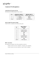
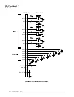
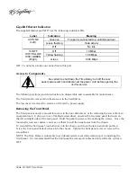
Gigabit Ethernet Indicators
The Gigabit Ethernet port NET1 has the following indicator LEDs:
Label
Indication
Meaning
Green on
The port is connected to a valid link partner
Green flashing
Data activity
ACT/LNK
(Left)
Off No
link
Off 10
Mbps
Yellow flashing
100 Mbps
10=OFF
100=YELLOW
1000=GREEN
(Right)
Green 1000
Mbps
NET 2 is not active. Make no connection to this port.
Access to Components
Be certain to shut down the Time Delay, turn off the rear
panel power switch and disconnect the power cord before opening the
unit for service.
The following sections provide instruction on disassembly and re-assembly for maintenance.
The front panel is removed to allow access to the hard drives.
The top cover is removed to service an I/O card or power supply.
Removing the Front Panel
The front panel is easily removed for access to the four disk drives, or for removing the server from an
equipment rack. Using a coin or a flat-blade screwdriver, unscrew the two large panel fasteners on
the left and right sides of the face panel. Hold the panel in place while undoing the screws. Since the
loosened screws are captive, you may use them to pull the panel away from the chassis.
To re-install the front panel, tuck all wires into the chassis and move the face panel into position.
Screw the front panel fasteners back into the chassis. Tighten the front panel access screws with a
screwdriver.
NOTE: The Time Delay is vulnerable to accidental system reset while removing or re-installing the
front panel. It is recommended that the front panel be removed or attached only while the system is
OFF.


