background image

26

27

2VV.

 Creating innovative solutions for you and your business since 1995.

ver.5 5-05-20

7. COMMISSIONING

  READ CAREFULLY

Please check the following points before putting 

the unit into operation:

● That  the  unit  is  fixed  well  to  the  supporting 

structure.

● That the unit is closed correctly and that a pipe 

or a rain louvre is installed to each neck to avoid 

contact with any rotating or heating component.

● That the electrical wiring is connected correctly, 

including grounding and protection against ex

-

ternal activation. 

● That all accessories are connected correctly.

● That the condensate drain is connected correctly 

to the discharge piping (for units with cooling).

● That  the  connection  is  in  compliance  with  in

-

structions in this manual.

● That no tool or other subject has been left inside 

the unit – this could lead to damage to the unit

  ATTENTION!

● Any interventions or modifications to unit wiring 

are prohibited and may lead to loss of warranty!

● We recommend to use accessories supplied by 

our company. If in doubt whether to use unori

-

ginal accessories, please contact 2VV.

7.1 ACTIVATION

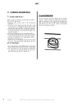
Put the unit into operation (Stand-by) by turning 

the main switch to position I (ON). When the main 

switch is turned on the control unit´s display li-

ghts up and the service data load. Service data 

will start to load. The unit is ready to start after 

the service data are loaded.

0

1

Содержание ALFA 95 II vertical

Страница 1: ...ver 5 5 05 20 ALFA 95 II EN v e r t i c a l Installation and operation Manual ...

Страница 2: ...ION 10 6 2 CONNECTING AIR INLETS 13 6 2 CONNECTING MECHANICAL ACCESSORIES 14 6 3 CONNECTING ELECTRICAL ACCESSORIES 15 6 4 CONNECTING CONDENSATE OUTLET 23 7 COMMISSIONING 26 7 1 ACTIVATION 26 8 MAINTENANCE 27 8 1 FILTER REPLACEMENT 27 8 2 CLEANING INTERVALS 27 9 REMOVING FAULTS 28 10 SERVICE 33 10 1 IF THE FAULT PERSISTS 33 10 2 PUTTING THE UNIT OUT OF OPERATION DISPOSAL 33 11 ACCESSORIES 33 12 WIR...

Страница 3: ...ecting the unit please read carefully and follow all the instructions below The manufacturer reserves the right to make changes including changes in the technical documentation without prior notification Please keep this manual for further references Consider this manual a permanent part of the product EC DECLARATION OF CONFORMITY The product was designed manufactured and placed on the market it c...

Страница 4: ...ycling options The separate collection and recycling of your product and its battery will help to preserve natural resources and ensure that the product will be recycled in a manner that protects human health and the environment x 2 ALFA 95 II 2 UNPACKING 2 1 CHECK THE SUPPLY READ CAREFULLY Upon delivery check the product packaging for possible damage If the packaging is da maged notify the carrie...

Страница 5: ... 800 1500 2500 3500 4500 5500 Controls Fan Main Switch Condensate outlet Access for filter maintenance Filter Filter To connect use CAT5 UTP cable CABLE NOT INCLUDED External temperature sensor Shielded cable max 50 m with a cross 0 5 mm CABLE NOT INCLUDED Water overflow sensor Contact On OFF Cable length 3 m ...

Страница 6: ...8 B 38 VERTICAL VERSION TYPE A B C C1 C2 D1 D2 E1 E2 F1 F2 G1 800 1594 668 878 862 348 274 424 246 397 129 104 318 1500 1894 749 1128 1095 386 424 474 398 447 153 111 454 203 C C1 C2 170 C1 A A 30 30 E2 D2 D1 E1 F2 F1 G1 G2 K2 V 75 40 G 1 2 I N 93 K1 B B 38 SION B C C1 C2 D1 D2 E1 E2 F1 F2 G1 G2 K1 668 878 862 348 274 424 246 397 129 104 318 108 217 749 1128 1095 386 424 474 398 447 153 111 454 60...

Страница 7: ... 186 137 590 82 2 1402 580 716 524 724 496 697 246 198 590 82 2 1402 580 716 524 1024 496 997 277 230 590 82 2 C2 C1 203 C C2 C1 172 A 30 A 30 100 V 110 K1 K2 40 B 38 B 38 G1 D2 E2 F1 AL VERSION A B C C1 C2 D1 D2 E1 E2 F1 F2 G1 2164 789 1427 367 700 524 524 496 496 149 106 60 2622 1058 1402 580 716 524 724 496 697 186 137 59 2622 1178 1402 580 716 524 724 496 697 246 198 59 2622 1542 1402 580 716 ...

Страница 8: ... 13 3 HR95 250 E 3 400 50 8300 12 0 HR95 350 E 3 400 50 11700 16 9 HR95 450 E 3 400 50 15000 21 7 HR95 550 E 3 400 50 18300 26 5 Electric reheater parameters Type Air flow m h Air heating C Total power kW Current A Number of phases Voltage V HR95 080 E 650 6 3 1 4 6 1 1 230 HR95 150 E 1500 5 3 2 7 11 8 1 230 HR95 250 E 2250 6 3 4 8 6 9 3 400 HR95 350 E 3500 5 4 6 4 9 3 3 400 HR95 450 E 4500 5 7 6 ...

Страница 9: ...ture after exiting the heat exchanger C HR95 080EC C 3 4 66 21 1 4 92 800 0 84 15 6 HR95 150EC C 3 4 83 14 1 8 43 1500 1 45 16 3 HR95 250EC C 1 102 20 2 13 87 2500 2 38 16 4 HR95 350EC C 1 1 2 70 21 2 21 61 3500 3 71 15 6 HR95 450EC C 1 1 2 84 12 5 25 1 4500 4 3 16 3 HR95 550EC C 1 1 2 64 24 4 35 24 5500 6 04 15 3 For water 7 12 and the inlet temperature 25 C Direct evaporator Cooling mode Type Ai...

Страница 10: ...ust soot grease toxins pathogenic or ganism etc The electric protection index of units is IP 43 de signed for outdoor environments 6 1 1 Access distances needed for servicing the unit 6 INSTALLATION 60 Type b 800 800 800 1000 1200 1500 a 1000 1000 1000 1100 1300 1600 c 100 100 100 100 100 100 a c b All dimensions in the table are in mm HR95 080 HR95 150 HR95 250 HR95 350 HR95 450 HR95 550 ...

Страница 11: ...rticular access to inspect dampers and the possibility to open them access to the control unit box cover to connections on the sides of the unit and to the air filter cover 6 1 2 Safe installation distance ATTENTION All materials used in a distance shorter than 100 mm from the ventilation unit must be non flammable they do not burn flame up burn out or little flammable they do not burn decompose e...

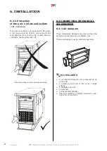
Страница 12: ...and dimen sions depending on the material of the ceiling and the unit s weight drill and drill bits of corresponding dimensions pliers and correct size spanner wrench Place the unit in a horizontal position then tilt it about 3 so that the condensate can drain away Fasten the unit with screws 6 INSTALLATION X Y A B 3500 V 885 2565 793 2200 4500 V 1005 2565 913 2200 5500 V 1368 2565 1276 2200 800 H...

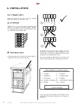
Страница 13: ...ach tran sition for rectangular circular pipes 4 sockets for connecting rectangular circular pipes accessories corresponding spanner sealing tape sealant READ CAREFULLY The connected ducts must have the same dimen sions as the unit s inlets and outlets Smaller diameter ducts may cause a decrease in the uni t s efficiency In some cases they may lead to shortening of the unit s lifetime Connect the ...

Страница 14: ... solid particles from coming into contact with the ventilator heating elements etc 6 3 CONNECTING MECHANICAL ACCESSORIES 6 3 1 Air dampers These rectangular dampers are used to close the air inlets connected to the ventilation unit These accessories must be ordered seperately YOU WILL NEED 2 rectangular dampers of corresponding di mensions 2 actuators with one or two wires voltage 230 V 8 M8 bolts...

Страница 15: ...y to follow all instruc tions in this manual and to comply with local laws and regulations The wiring diagrams depicted on the product take precedence over diagrams in this manual Before connecting the wiring make sure that terminal indications match the diagram If in doubt contact the supplier and do not connect the unit If the product is connected to other then original control system contact th...

Страница 16: ...abel in stalled on the control device casing Pe L1 L2 L3 N All phases of the electric power supply must be connected through the corresponding type of cir cuit breaker The distance between disconnected contacts must be larger than 3 mm It must be possible to disconnect the unit from the electric power supply with a single power switch The unit must be connected to TN S network this means that the ...

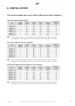
Страница 17: ...e Type of circuit breaker A HR95 080 E 1 230 1400 8 7 3Cx1 5 16 HR95 150 E 1 230 2700 18 3Cx2 5 20 HR95 250 E 3 400 4800 13 1 5Cx1 5 16 HR95 350 E 3 400 6500 12 9 5Cx1 5 16 HR95 450 E 3 400 7700 14 6 5Cx1 5 16 HR95 550 E 3 400 10700 21 5Cx2 5 25 Recommended values values must be specified by the person responsible for the wiring in the building e g designer with regard to parameters of the power l...

Страница 18: ... 1 20 1 21 1 22 1 9 1 8 1 20 1 21 1 22 1 18 1 19 2 3 4 5 6 7 8 9 10 11 EN RU 1 A 1 4 SAFETY THERMOSTAT POSTHEATING ЗАЩИТНЫЙ ТЕРМОСТАТ НАГРЕВАТЕЛЯ 2 A 2 3 SAFETY PREHEATING THERMOSTAT ЗАЩИТНЫЙ ТЕРМОСТАТ ПРЕДВАРИТЕЛЬНОГО НАГ 3 A 5 6 LF1 FLAP INLET output L open LF2 FLAP OUTLET output L open LF1 ЗАСЛОНКА ВПУСК выход L открыт LF2 ЗАСЛОН 4 A 7 8 RUN CONTACT output NO NC settable RUN контакт выход NO NC...

Страница 19: ...NC nastavitelné ERROR KONTACT výstup NO А 11 Lint 12 Lout VODNÍ ČERPADLO PŘEDEHŘEVU 11 Lint 12 Lout BOOST vstup NO FIRE vstup NC EXTERNÍ OVLÁDÁNÍ ON OFF vstup NC ČIDLO KVALITY VZDUCHU 0 10V vstup VODNÍ ČERPADLO 1 Lint 2 Lout мый выход ON OFF ŘÍZENÍ TEPELNÉHO ČERPADLA nastavitelné výstup ON OFF ADIABATICKÝ MODUL výstup ON OFF B 1 1 1 22 0 RU CZ ЕВАТЕЛЯ BEZPEČNOSTNÍ TERMOSTAT DOHŘEVU ВАРИТЕЛЬНОГО НА...

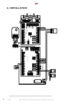
Страница 20: ...4 2 FUSE Room Int2 Int1 Ext3 Fan Out Ext2 Ext1 CO2 Fan In CONTROL PANEL N DC12V PE PWM GND RPM RPM GND PWM RELAY BYPP SSR SSR BOOST PIR EXT FLAP RUN PREH POST FIRE RELAY RELAY RELAY RELAY GND 0 10 GND GND 1 2 3 4 5 6 7 8 9 11 10 12 13 14 15 16 17 18 19 20 21 22 23 24 IN 1 IN 2 L L LF1 LF2 ERR COOL ALARM HEAT HEAT L L Fu 57 58 59 60 61 62 32 31 56 55 54 53 52 51 50 48 49 47 46 45 44 43 42 41 40 39 ...

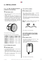
Страница 21: ...95 450 EOKO 560 12 0 3 D 12 17 3 HR95 550 EOKO 630 24 0 3 D 24 34 7 6 4 2 2 External control TECHNICAL DATA Low voltage switching contact maximum possi ble contact load 12 V 0 4 A CABLE cable with two conductors with a min cross section of 0 5 mm2 Maximum length of 50 m The contact is normally closed When opening the contact the unit turns off This accessory is sold seperately 6 4 2 3 Fire contact...

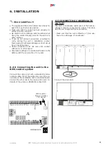
Страница 22: ...f 50 m Contact is normally open When connected the ventilation unit operates according to the pre set ventilation output The required output can be set in the service menu Chapter 7 6 2 6 4 3 Control unit To activate the unit it is necessary to connect the control display panel and the unit using a control cable data cable slacken the bolt on the bottom of the display panel open the case of the di...

Страница 23: ...nit to the BMS control system Connect the control unit with a standard commu nication cable Insert the cable into one of the co nnectors on the ventilation unit s electronic board Connect the other end to the main control unit For details of the protocol ModBUS contact 2VV 6 INSTALLATION panel 1 1 1 5 1 6 1 2 1 7 1 8 1 9 1 10 1 11 1 12 1 13 1 14 1 15 1 16 1 17 1 3 1 4 1 20 1 21 1 22 1 18 1 19 EN R...

Страница 24: ...ȚȘȖȓȤȕȖȋȖ țșȚȘȖȑșȚȊȈ Ȑș ȗȖȓȤȏțȑȚȍ șȚȈȕȌȈȘȚȕȣȑ ȒȈȉȍȓȤ ȒȖȔȔțȕȐȒȈȞȐȐ ǪșȚȈȊȤȚȍ ȒȈȉȍȓȤ Ȋ ȖȌȐȕ Ȑȏ ȒȖȕȕȍȒȚȖȘȖȊ ȕȈ ȥȓȍȒ ȚȘȖȕȕȖȑ ȗȓȈȚȍ ȊȍȕȚȐȓȧȞȐȖȕȕȖȋȖ țșȚȘȖȑșȚȊȈ ǪȚȖȘȖȑ ȒȖȕȍȞ ȗȖȌșȖȍȌȐȕȐȚȍ Ȓ ȋȓȈȊȕȖȔț ȉȓȖȒț țȗȘȈȊȓȍȕȐȧ ǯȈ ȗȖȌȘȖȉȕȖȑ ȐȕȜȖȘȔȈȞȐȍȑ Ȓ ȗȘȖ ȚȖȒȖȓț 0RG 86 ȖȉȘȈȚȐȚȍșȤ ȕȈ ȜȐȘȔț 99 ɑɂɌȺɃɌȿ ȼɇɂɆȺɌȿɅɖɇɈ ǻșȚȘȖȑșȚȊȖ ȔȖȎȕȖ ȗȖȌȒȓȦȟȐȚȤ Ȓ șȐșȚȍȔȍ țȗȘȈȊ ȓȍȕȐȧ 7 7 Ȑ ȖȌȕȖȊȘȍȔȍȕȕȖ Ȓ ȉȓȖȒț țȗȘȈȊ ȓȍȕȐȧ țșȚȘȖȑșȚȊȖȔ ǷǶǬǹ...

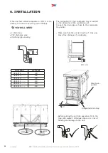
Страница 25: ... in the unit and connect it to the regulation Water overflow sensor connect to terminals 17 18 on control board B Water overflow sensor conect to terminals 17 18 on control board B If the unit has a C O exchanger or a DX exchan ger you can optionally connect another water overflow sensor to the condensing bath of the exchanger coil B Optionally you can connect water overflow sensor included in the...

Страница 26: ...ate drain is connected correctly to the discharge piping for units with cooling That the connection is in compliance with in structions in this manual That no tool or other subject has been left inside the unit this could lead to damage to the unit ATTENTION Any interventions or modifications to unit wiring are prohibited and may lead to loss of warranty We recommend to use accessories supplied by...

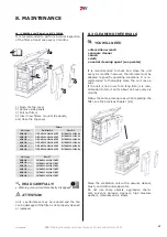
Страница 27: ...ommended to perform a visual inspection of the filter at least once every 3 months 1 Open the top cover 2 Remove side panels 3 Pull out filters 4 Insert new filters mount side panels and close the top cover Unit type Unit type Filters filter F7 Pre filter G4 filter G4 READ CAREFULLY Warning icon will automatically disappear ATTENTION Unit s performance may be reduced and the fan can be damaged if ...

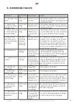
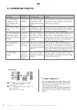
Страница 28: ...logged Unit is venti lating Clogged filter Check the condition of the filter or replace it If the unit does not have a pressure sensor for the filter RESET the clogged filter according to the manual 8 Failure in preheating 1 Unit is venti lating Overheated electric ex changer or damaged sensor Open the exchanger ther mostat Check that air can flow freely through the unit electric heat exchanger is...

Страница 29: ...t it measuring its resi stance the resistance value at 20 C is around 10kW 18 Inlet Tempe rature sensor failure in the supply canal T EXT3 Unit is not working Room temperature sensor failure Check that the sensor is correctly connected to the electronics or test it measuring its resi stance the resistance value at 20 C is around 10kW 19 Inlet Tempe rature sensor failure after the second ex changer...

Страница 30: ...upply point for mechanical da mage or whether it is clogged by dirt or whe ther the supply hoses are free The pressure sensor will likely need to be replaced 27 Failure in the pressure sensor of the inlet filter Unit is venti lating Pressure sensor failure Check the supply point for mechanical da mage or whether it is clogged by dirt or whe ther the supply hoses are free The pressure sensor will l...

Страница 31: ...eri pherals connected to Module B Unable to communicate with module B Check whether the communication cable between motherboards A and B is damaged If necessary replace module B 37 Condensate pan overflow Unit is not working The level sensor has detected an extremely high le vel of water in the condenser s pan Check that the level sensor is connected co rrectly or check that it is operating correc...

Страница 32: ...O NC settable RUN контакт выход NO NC устанавливаемый RUN KONTACT výstup NO NC nastavitelné 3 A 9 10 ERROR CONTACT output NO ОШИБКА КОНТАКТА выход NO ERROR KONTACT výstup NO 4 A 11 12 PREHEATER WATER PUMP 11 Lint 12 Lout ВОДЯНОЙ НАСОС ПРЕДВАРИТЕЛЬНОГО НАГРЕВА 11 Lint 12 Lout VODNÍ ČERPADLO PŘEDEHŘEVU 11 Lint 12 Lout 5 A 13 14 BOOST input NO BOOST вход NO BOOST vstup NO 6 A 15 16 FIRE input NC FIRE...

Страница 33: ... be dismantled in a specialised centre so that the recyclable materials can be re used Parts that cannot be recycled in should be taken to a legal waste disposal site Materials must be disposed of in accordance with applicable national regulations and directives 11 ACCESSORIES The original accessories to ALFA 95 unit EOKO 250 3 0 3D EOKO 355 7 5 3D EOKO 400 7 5 3D EOKO 560 12 0 3D EOKO 560 12 0 3D...

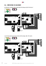
Страница 34: ...Room Int2 Int1 Ext3 Fan Out Ext2 Ext1 CO2 Fan In N DC12V PE PWM GND RPM RPM GND PWM RELAY BYPP SSR SSR BOOST PIR EXT FLAP RUN PREH POST FIRE RELAY RELAY RELAY RELAY GND 0 10 GND GND 1 2 3 4 5 6 7 8 9 11 10 12 13 14 15 16 17 18 19 20 21 22 23 24 IN 1 IN 2 L L LF1 LF2 ERR COOL ALARM HEAT HEAT L L Fu 57 58 59 60 61 62 32 31 56 55 54 53 52 51 50 48 49 47 46 45 44 43 42 41 40 39 38 37 36 35 34 33 27 28...

Страница 35: ...ater pump for coil 2 0 10V 1 24V GND GND El mixing valve for coil 2 24V 0 10V U 2 3 5 unit with electric heating coil unit without electric exchanger with external C O exchanger FUSE Room Int2 Int1 Ext3 Fan Out Ext2 Ext1 CO2 Fan In N DC12V PE PWM GND RPM RPM GND PWM RELAY BYPP SSR SSR BOOST PIR EXT FLAP RUN PREH POST FIRE RELAY RELAY RELAY RELAY GND 0 10 GND GND 1 2 3 4 5 6 7 8 9 11 10 12 13 14 15...

Страница 36: ...2 DX 0 10V NTC Unit Electric DX 0 10V COOL HEAT DEFROST ERROR 0 10V unit with electrical heating coil and second external DX exchanger with 0 10V control FUSE Room Int2 Int1 Ext3 Fan Out Ext2 Ext1 CO2 Fan In N DC12V PE PWM GND RPM RPM GND PWM RELAY BYPP SSR SSR BOOST PIR EXT FLAP RUN PREH POST FIRE RELAY RELAY RELAY RELAY GND 0 10 GND GND 1 2 3 4 5 6 7 8 9 11 10 12 13 14 15 16 17 18 19 20 21 22 23...

Страница 37: ... 1 2 3 5 0 10V 24V 0 10V U 0 10V 1 24V GND GND El mixing valve for coil 2 24V 0 10V U 2 3 5 unit with water exchanger and second water external exchanger for water cooling unit with water exchanger and second external electric heating coil FUSE Room Int2 Int1 Ext3 Fan Out Ext2 Ext1 CO2 Fan In N DC12V PE PWM GND RPM RPM GND PWM RELAY BYPP SSR SSR BOOST PIR EXT FLAP RUN PREH POST FIRE RELAY RELAY RE...

Страница 38: ...R DX OFF ON 1 24V GND GND 2 3 5 0 10V 24V 0 10V U unit with water exchanger and second external DX exchanger with OFF ON control FUSE Room Int2 Int1 Ext3 Fan Out Ext2 Ext1 CO2 Fan In N DC12V PE PWM GND RPM RPM GND PWM RELAY BYPP SSR SSR BOOST PIR EXT FLAP RUN PREH POST FIRE RELAY RELAY RELAY RELAY GND 0 10 GND GND 1 2 3 4 5 6 7 8 9 11 10 12 13 14 15 16 17 18 19 20 21 22 23 24 IN 1 IN 2 L L LF1 LF2...

Страница 39: ... M AC MODUL JP4 64 65 66 63 GND 12 B A Unit DX 0 10V DX 0 10V COOL HEAT DEFROST ERROR 0 10V unit with DX 0 10V exchanger unit with DX exchanger control OFF ON FUSE Room Int2 Int1 Ext3 Fan Out Ext2 Ext1 CO2 Fan In N DC12V PE PWM GND RPM RPM GND PWM RELAY BYPP SSR SSR BOOST PIR EXT FLAP RUN PREH POST FIRE RELAY RELAY RELAY RELAY GND 0 10 GND GND 1 2 3 4 5 6 7 8 9 11 10 12 13 14 15 16 17 18 19 20 21 ...

Страница 40: ...P3 JP2 JP1 JTAG JP4 JP3 JP2 JP1 AC5 M AC MODUL JP4 AC5 M AC MODUL JP4 64 65 66 63 GND 12 B A NTC Coil 2 ELECTRIC Unit DX OFF ON EOKO2 0 10V 230V 230V L N POSTHEAT 2 OFF ON COOL HEAT DEFROST ERROR DX OFF ON FUSE Room Int2 Int1 Ext3 Fan Out Ext2 Ext1 CO2 Fan In N DC12V PE PWM GND RPM RPM GND PWM RELAY BYPP SSR SSR BOOST PIR EXT FLAP RUN PREH POST FIRE RELAY RELAY RELAY RELAY GND 0 10 GND GND 1 2 3 4...

Страница 41: ...oil 2 WATER L N 230V W PUMP Postheater L N NTC Water OUT Unit DX OFF ON Water pump for coil 2 OFF ON COOL HEAT DEFROST ERROR DX OFF ON 0 10V 1 24V GND GND El mixing valve for coil 2 24V 0 10V U 2 3 5 FUSE Room Int2 Int1 Ext3 Fan Out Ext2 Ext1 CO2 Fan In N DC12V PE PWM GND RPM RPM GND PWM RELAY BYPP SSR SSR BOOST PIR EXT FLAP RUN PREH POST FIRE RELAY RELAY RELAY RELAY GND 0 10 GND GND 1 2 3 4 5 6 7...

Страница 42: ...M AC MODUL JP4 64 65 66 63 GND 12 B A NTC L N 230V W PUMP Postheater L N Unit VCO Coil 2 ELECTRIC EOKO2 0 10V 230V 230V L N Water pump for coil 1 POSTHEAT 2 1 24V GND GND El mixing valve for coil 1 2 3 5 0 10V 24V 0 10V U FUSE Room Int2 Int1 Ext3 Fan Out Ext2 Ext1 CO2 Fan In N DC12V PE PWM GND RPM RPM GND PWM RELAY BYPP SSR SSR BOOST PIR EXT FLAP RUN PREH POST FIRE RELAY RELAY RELAY RELAY GND 0 10...

Страница 43: ... and follow its in structions to ensure correct and safe operation of the heat recovery unit Should you have any questions or require some additional explanation please do not hesitate to contact our sales department or technical support Contact information 2VV s r o Fáblovka 568 533 59 Pardubice Czech Republic Internet http www 2vv cz ...

Страница 44: ...y damage to the product arising from unauthorised installation and operation inconsistent with regular conventions for installation and operation of air conditioning units and regulation systems Attach the label which you can find in accessories for future troubleshooting ...

Отзывы: