


24
EN
Motherboard Installation
Every motherboard has different specifications for the installment of stand-offs, it is
strongly recommended that you refer to your motherboard’s instruction manual when
nstalling stand-offs to the case.
Power Supply Installation
Securely install the power supply at the top of the case and tighten it with screws on
position .
Graphics Card Installation
Install the graphics card on the PCI slot following the indicated direction and tighten it
with screws
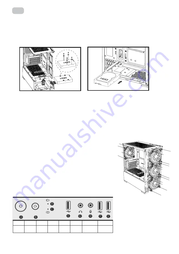
3.5’’ HDD Installation
Install the HDD on the indicated position and tighten it with screws.
2.5’’ SSD Installation
Install the SSD on the indicated positions and tighten them with screws
Fans Installation
Front: 120mm fan x 3
Rear: 120mm fan x 1
HDD Installation
(
1
)
HDD Installation
(
2
)
SSD Installation
(
1
)
SSD Installation
(
2
)
(
1
)
Встановлення HDD (3,5’’ bay).
1.
Determine the location of the HDD in the case.
2.
Place the HDD in proper location.
3.
Secure HDD with screws.
Fan Installation on front panel.
1.
Front fan installation (А).
2.
3x120mm ARGB fans are installed in the case on the front panel.
3.
LED of the ARGB fans is controlled by a controller with a remote.
4.
4. Fans connection - 6 pin (to the controller).
Fan Installation on rear panel.
1.
Rear fan installation (В).
2.
1x120mm ARGB fan is installed in the case on the rear panel.
3.
Fan connection - 6 pin (to the controller).
Motherboard Installation
Every motherboard has different specifications for the installment of stand-offs, it is
strongly recommended that you refer to your motherboard’s instruction manual when
nstalling stand-offs to the case.
Power Supply Installation
Securely install the power supply at the top of the case and tighten it with screws on
position .
Graphics Card Installation
Install the graphics card on the PCI slot following the indicated direction and tighten it
with screws
3.5’’ HDD Installation
Install the HDD on the indicated position and tighten it with screws.
2.5’’ SSD Installation
Install the SSD on the indicated positions and tighten them with screws
Fans Installation
Front: 120mm fan x 3
Rear: 120mm fan x 1
HDD Installation
(
1
)
HDD Installation
(
2
)
SSD Installation
(
1
)
SSD Installation
(
2
)
(
1
)
A
B
I/O Ports, buttons, indicators.
A
B
C
D
E
F
G
H
Power
Button
Reset
Button
Power
LED
HDD
LED
USB 3.0
USB 2.0
Headphone
Jack
Microphone
Jack
Содержание GAMING CALLEO WHITE
Страница 1: ...RU UA EN COMPUTER CASE OPERATION GUIDE 2E GAMING CALLEO WHITE GB700W...
Страница 8: ...8 RU ARGB LED...
Страница 10: ...10 UA 1 2 3 4 5 6 1 2 3 4 3 CR2025...
Страница 17: ...17 RU ARGB LED...
Страница 19: ...19 RU 1 2 3 4 5 6 1 2 3 4 3 2025...
Страница 25: ...25 EN ARGB FAN CONNECTION DIAGRAM INSTRUCTION ARGB fan connection diagram Power supply LED light bar...
Страница 29: ...2 1 2 3 4 5 6 12 _____________________________________________________________...