


LCD KVM Console User Manual
17
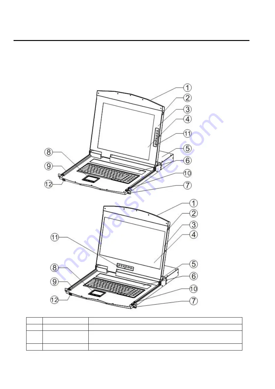
Parts
Front View
According to the size of the LCD screen is divided into two styles, as shown below, the components of the
description please see the figure after the serial number table describes the details.
No
Part
Function Description
1
Upper handle
Pull the handle, slide the LCD module out and push it in
2
Lock
Used to lock the LCD module, pull out the module must first
unlock, push into the automatic locking
3
LCD screen cover Can be opened or closed with the handle, opening and closing
Содержание AS-7100 Series
Страница 21: ...LCD KVM Console User Manual 21 Front view of the 4 3 screen dual rail 17inch 4 3 screen 19inch 4 3 screen...
Страница 22: ...LCD KVM Console User Manual 22 Dual Rail Slide View Dual rail overall rear view...
Страница 23: ...LCD KVM Console User Manual 23 Overall Dimensions of the LCD KVM Single rail single port KVM Console dimension...
Страница 24: ...LCD KVM Console User Manual 24 Single rail multi ports KVM Console dimension...
Страница 25: ...LCD KVM Console User Manual 25 Dual rail LCD KVM Console dimension...
Страница 30: ...LCD KVM Console User Manual 30 Mounting and fixing in the bracket tail...
Страница 40: ...LCD KVM Console User Manual 40 Installation of Single Port LCD KVM Switch...
Страница 45: ...LCD KVM Console User Manual 45 VGALCD KVM Switch Cascade CAT5LCD KVM Switch Cascade...


