Zubler Z1 CAM, Manual
The Zubler Z1 CAM is a high-quality dental milling machine designed for precise and efficient production of dental restorations. To ensure proper usage of this advanced equipment, users can easily access the free manual for download on our website. Experience superior craftsmanship with the Zubler Z1 CAM. Download manual from manualshive.com.
Share
Download


Reviews:
No comments
Related manuals for Z1 CAM
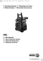
FEC
Brand: Abicor Binzel Pages: 116
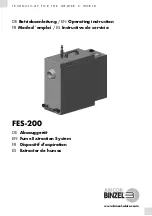
FES-200
Brand: Abicor Binzel Pages: 100

Encore l17
Brand: Clarke Pages: 58

SAA 901
Brand: Holzstar Pages: 18

ZI-ASA550
Brand: Zipper Mowers Pages: 15

9120039238463
Brand: Zipper Mowers Pages: 52

SW1 450M ECO
Brand: Wirbel Pages: 186

L14
Brand: FIORENTINI Pages: 8

BD 40/12 C
Brand: Kärcher Pages: 374

Diversey ULTIMAXX 1900
Brand: Taski Pages: 546

cm mini orbital
Brand: comoc Pages: 52

RS26L+
Brand: Ice Pages: 40

Flex 3 FLX3
Brand: Windsor Pages: 45

FSL100
Brand: Full Spectrum Laser Pages: 12

3.126.015
Brand: Dibo Pages: 22

3.126.160
Brand: Dibo Pages: 27

BHPC210
Brand: Black+Decker Pages: 8


