


Reviews:
No comments
Related manuals for Match LWR50L-21 Series

m Bot mega
Brand: Makeblock Pages: 14

Powerman Kid ROB90EN
Brand: LEXIBOOK Pages: 2

Robotics BT Beginner
Brand: fischertechnik Pages: 60

4 Robotics Kit
Brand: Pi-top Pages: 6

DARwIn OP
Brand: RoMeLa Pages: 56

IRB 120
Brand: ABB Robotics Pages: 24

MS6MT
Brand: QKM Pages: 52

Arduino Robotics Kit With Motor Shield
Brand: oddWires Pages: 28

ESAB W82
Brand: ABB Pages: 34

ROBO MAX TR41573
Brand: Spectron Toys Pages: 12

GRIPKIT CR EASY
Brand: WEISS ROBOTICS Pages: 40

5010011
Brand: WEISS ROBOTICS Pages: 61
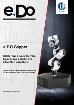
e.DO
Brand: Comau Pages: 28

C5G-R1C
Brand: Comau Pages: 82

Advanced Robotics Set
Brand: Tinkerbots Pages: 60


