background image

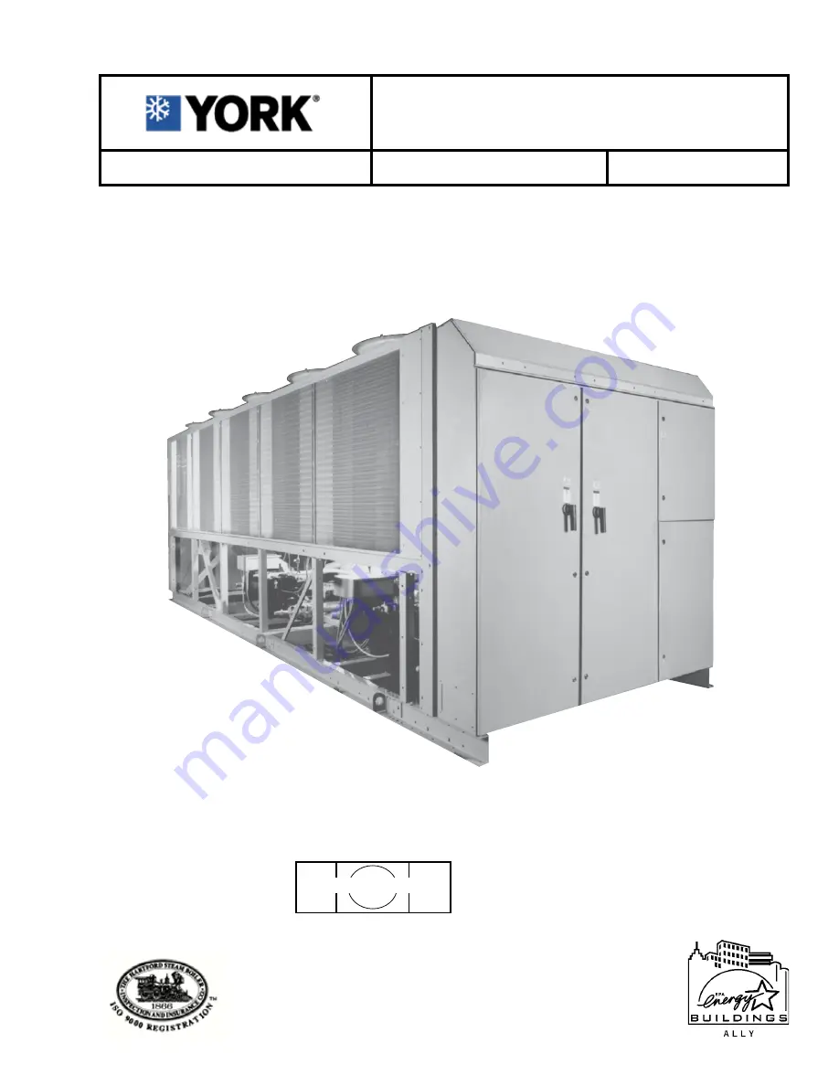
YCAS AIR-COOLED LIQUID CHILLERS

YCAS0098EB through YCAS0208EB

YCAS 2 SYSTEM EPROM

031-01798-001

(STANDARD, BRINE & METRIC MODELS COMBINED)

28971AR

60 Hz

AIR-COOLED SCREW LIQUID CHILLERS

INSTALLATION, OPERATION, MAINTENANCE

Supersedes: 201.18-NM7 (916)

Form 201.18-NM7 (1020)

Issue Date: 

October 2, 2020

Summary of Contents for YCAS 0138EB

Page 1: ...hrough YCAS0208EB YCAS 2 SYSTEM EPROM 031 01798 001 STANDARD BRINE METRIC MODELS COMBINED 28971AR 60 Hz AIR COOLED SCREW LIQUID CHILLERS INSTALLATION OPERATION MAINTENANCE Supersedes 201 18 NM7 916 Fo...

Page 2: ...any referenced materials This in dividual shall also be familiar with and comply with all applicable industry and governmental standards and regulations pertaining to the task in question SAFETY SYMB...

Page 3: ...ny work on the chiller REVISION NOTES Revisions made to this document are indicated in the following table These revisions are to technical information and any other changes in spelling grammar or for...

Page 4: ...gle Point Power Connection with Individual Circuit Protection 23 Single Point Power Connection with Combined Circuit Protection 23 Single Point Power Connection without Circuit Protection 23 Control C...

Page 5: ...upply Connection to Factory Circuit Breaker 56 Compressor Data 57 Fan Data 57 Electrical Notes 58 Wiring Diagram Across the Line Start 60 Elementary Diagram Across the Line Start 62 Wiring Diagram Wye...

Page 6: ...vaporator Heater Control 130 1 18 Pumpdown LLSV Control 130 1 19 Alarms 130 1 20 Run Status Chiller 131 1 21 Lead Lag Compressor Selection 131 2 STATUS KEY GENERAL STATUS MESSAGES FAULT WARNINGS 132 2...

Page 7: ...8 2 Program Key User Programmable Values 160 8 3 Programming Default Values 164 8 4 4 Condenser Fan Control 165 SECTION 9 MAINTENANCE 169 General Requirements 169 Daily Maintenance 169 Scheduled Maint...

Page 8: ...ted by evidence that the failure has occurred within the warranty period and that the unit has been operated within the designed parameters specified All warranty claims must specify the unit model se...

Page 9: ...le for purposes other than those specified in these instructions Any use of the equipment other than its intended use or operation of the equipment contrary to the relevant procedures may result in in...

Page 10: ...ety hazards Use of gloves and safety glasses are however recommended when working on the unit The build up of refrigerant vapor from a leak for example does pose a risk of asphyxiation in confined or...

Page 11: ...hr TWA exposure limits Stability Not specified Conditions to avoid Use in presence of naked flames red hot surfaces and high moisture levels Hazardous reactions May react violently with sodium potass...

Page 12: ...when burned Burning may evolve irritating noxious fumes Respiratory protection Use in well ventilated areas ventilate locally Protective clothing Goggles or face shield should be worn Gloves not neces...

Page 13: ...itrogen highly recommended Section 4 PHYSICAL DATA Appearance Clear liquid gray to yellow or light brown tint Boiling Point 650 F Vapor Pressure 0 01 mmHg 20 C Specific Gravity water 1 0 94 0 97 Volat...

Page 14: ...tection Use in well ventilated area Ventilation Local exhaust Protective Gloves Strongly recommended especially for prolonged exposure Eye Face Protection Goggles Firefighters should use NIOSH MNSA ap...

Page 15: ...non metallic conduit General Description TheAir Cooled Screw Chiller utilizes many components which are the same or nearly the same as a standard reciprocating chiller of a similar size This includes...

Page 16: ...parator The pressur ized oil is then cooled in the condenser coils and piped back to the compressor for lubrication The compressor design working pressure is 450 PSIG 31 bar Each chiller receives a 30...

Page 17: ...cy The oil also provides cooling by transferring much of the heat of compression from the gas to the oil keeping discharge temperatures down and reducing the chance for oil breakdown Oil injected into...

Page 18: ...eliminate chiller failure due to AC power failure The Programmed Setpoint is stored in lithium battery backed memory Motor Current Protection The microprocessor motor protection provides high cur rent...

Page 19: ...low motor current and shuts the system down The micro will try two more starts before locking the system out The system locks out because the motor protector is a manual reset device After the first...

Page 20: ...e measured half line current The Operating Current is given by 0 65 X factory overload current setting An unloaded compressor condition occurs when any measured half line current is less than the Oper...

Page 21: ...1 122 0 1 1 1 1 0 1 0 17 168 2 113 0 1 1 1 0 0 0 1 0118 28 146 2 197 1 1 0 0 0 1 0 1 SYS 2 40 88 1 119 0 1 1 1 0 1 1 1 46 73 1 99 0 1 1 0 0 0 1 1 58 59 1 80 0 1 0 1 0 0 0 0 17 233 2 157 1 0 0 1 1 1 0...

Page 22: ...101 1 136 1 0 0 0 1 0 0 0 58 81 1 109 0 1 1 0 1 1 0 1 17 320 4 108 0 1 1 0 1 1 0 0 28 278 2 188 1 0 1 1 1 1 0 0 0178 40 169 2 114 0 1 1 1 0 0 1 0 46 140 2 189 1 0 1 1 1 1 0 1 58 111 1 150 1 0 0 1 0 1...

Page 23: ...elay is enabled by the microprocessor from Relay Output Board 1 Terminal 8 SYS 1 or Relay Output Board 2 Terminal 6 SYS 2 The 1TR SYS 1 or 2TR SYS 2 contacts open de energizing 1S SYS 1 or 2S SYS 2 1M...

Page 24: ...cop per tubes and galvanized steel supports for generally adequate corrosion resistance However these materials are not adequate for all environments Entry Used to confirm Set Point changes cancel inp...

Page 25: ...o 121 C with 1 NPT IPS connection for upright mounting in horizontal pipe A flow switch must be field installed with each unit Star Delta Compressor Motor Starter Provides approximately 65 reduced inr...

Page 26: ...380 3 60 460 3 60 575 3 60 Wye Star Delta Across the Line Design Series F Engineering Change or PIN Level BASIC PART NUMBER 1 2 3 4 5 6 7 8 9 10 11 12 13 14 15 BASE PRODUCT TYPE NOMINAL CAPACITY UNIT...

Page 27: ...prene Pads 38 39 40 41 42 43 44 45 46 47 48 49 50 51 52 53 54 3 X 1 D C 2 W B 3 V P 4 S X 5 M 6 A 7 S 8 F E T X I B P L R H X S 1 S N UNIT NOMENCLATURE NAMEPLATE ENGINEERING DATA OPTIONS SECTION OF PA...

Page 28: ...site It is recommended that the unit is periodically in spected during storage INSPECTION Remove any transit packing and inspect the unit to en sure that all components have been delivered and that n...

Page 29: ...29 JOHNSON CONTROLS FORM 201 18 NM7 88 2250mm UNIT RIGGING CORRECT WRONG LD03514A FIG 3 UNIT RIGGING CORRECT WRONG LD03515 FIG 4 LIFTING LUGS CORRECT WRONG Handling and Storage...

Page 30: ...ble strength The channels should be spaced at the same centres as the vibration mounting holes in the unit base frame and must be at least 4 3 4 120 mm wide at the contact points This will allow vibra...

Page 31: ...on is provided on page 106 SHIPPING BRACES The chiller s modular design does not require shipping braces PIPEWORK CONNECTION General Requirements The following piping recommendations are intended to e...

Page 32: ...he insulation is recommended supplied independently and controlled by an ambient temperature thermostat set to switch on at 37 F 21 C above the freezing tem perature of the liquid The liquid circulati...

Page 33: ...pe Precautions should be taken to ensure that the outlet of relief valves vent pipe remain clear of obstructions at all times DUCTWORK CONNECTION General Requirements The following ductwork recommenda...

Page 34: ...urrent protection devices between the supply conductors and the power supply terminals on the unit To ensure that no eddy currents are set up in the power panel the cables forming each 3 phase power s...

Page 35: ...39 and 40 close to start the chilled liquid pump This contact can be used as a master start stop for the pump in conjunction with the daily start stop schedule Run Contact Terminals 29 and 30 Figs 12...

Page 36: ...36 JOHNSON CONTROLS POWER AND CONTROL PANEL LAYOUTS WYE DELTA TYPICAL FIG 8 POWER PANEL SECTION 00263VIP 4...

Page 37: ...37 JOHNSON CONTROLS FORM 201 18 NM7 FIG 9 OPTION PANEL SECTION OPTION PANEL LAYOUT TYPICAL 00246VIP Installation...

Page 38: ...ION LAYOUT LOGIC SECTION LAYOUT 00247VIP ITEM 1 2 3 4 5 6 7 8 9 DESCRIPTION Microprocessor Board Back of Keypad Back of Display I O Expansion Board 1 Power Supply Board Relay Output Board 1 Relay Outp...

Page 39: ...39 JOHNSON CONTROLS FORM 201 18 NM7 FIG 11 LOGIC SECTION LAYOUT WITH CONTROL PANEL LAYOUT LOGIC SECTION LAYOUT WITH CONTROL PANEL LAYOUT 00248VIP Installation...

Page 40: ...CY STOPS TERMINALS 13 19 TERMINALS 23 38 Print Temperature PWM Current PWM Flow Switch System No 1 Run System No 2 Run 14 15 16 17 18 19 23 24 25 26 27 28 29 30 System No 1 Alarm Contacts Chilled Liqu...

Page 41: ...13 CUSTOMER CONNECTIONS CUSTOMER CONNECTIONS TRANSFORMERS POWER SUPPLY BOARD CIRCUIT BREAKERS RELAY BOARDS I O EXPANSION BOARD CUSTOMER CONNECTIONS Flow Switch Alarm Run etc MICROPROCESSOR CIRCUIT BO...

Page 42: ...ounted in the options panel It is important to check that the correct primary tapping has been used With the supply to the unit isolated remove the lid to the transformer box COMMISSIONING PREPARATION...

Page 43: ...he cooler outlet and wired into the control panel correctly using shielded cable There should be a straight run of at least 5 pipe diameters on either side of the flow switch The flow switch should be...

Page 44: ...lumn of liquid Fan Rotation As discharge pressure rises the condenser fans operate in stages to control the pressure Verify that the fan operation is correct for the type of unit Suction Superheat Che...

Page 45: ...ed all operations are fully automatic After an initial period at minimum capacity on the lead compressor the control system will adjust the unit load depending on the chilled liquid tempera ture and r...

Page 46: ...s Special care must be taken not to exceed the maximum allowed A Correction Factor B Mean Temperature through Cooler C Concentration W W COOLER WATER PRESSURE DROP ENGLISH UNITS LD03504A COOLER WATER...

Page 47: ...7 7 50 0158 4 4 12 8 11 3 48 5 17 7 50 0178 4 4 12 8 11 3 48 5 17 7 50 0198 4 4 12 8 11 3 48 5 17 7 50 0208 4 4 12 8 11 3 48 5 17 7 50 NOTES 1 For leaving brine temperature below 40 F contact your nea...

Page 48: ...8 2 1 8 2 1 8 Fan Motor Speed revs min 1140 0 1140 0 1140 0 1140 0 1140 0 1140 0 1140 0 1140 0 1140 0 Fan Diameter inches 35 4 35 4 35 4 35 4 35 4 35 4 35 4 35 4 35 4 Fan Tip Speed ft min 10 575 10 57...

Page 49: ...Fans Fan Motor HP kW 2 1 8 2 1 8 2 1 8 2 1 8 2 1 8 2 1 8 2 1 8 2 1 8 2 1 8 Fan Motor Speed revs sec 19 0 19 0 19 0 19 0 19 0 19 0 19 0 19 0 19 0 Fan Diameter mm 900 900 900 900 900 900 900 900 900 Fa...

Page 50: ...50 JOHNSON CONTROLS This page intentionally left blank...

Page 51: ...PRESS FANS OPTION 1 85 PRESSURE Pa HIGH PRESS FANS OPTION 2 150 SLOW SPEED FANS 10 ELECTRICAL THREE PHASE 60 Hz V 200 230 380 460 575 440 OPERATING LIMITATIONS SI UNITS Maximum Ambient w High Ambient...

Page 52: ...500 2 3 0 250 2 3 0 250 202 481 1518 4 7 8 38 0 0138EB 380 172 200 225 250 2 4 0 4 300 4 300 122 285 900 4 4 8 23 0 460 142 150 175 225 2 4 0 4 300 4 300 101 228 719 4 4 0 19 0 575 113 150 150 175 6 1...

Page 53: ...00 500 2 0 500 2 3 0 250 2 3 0 250 233 591 1866 4 8 2 33 0 230 284 400 350 450 2 0 500 2 3 0 250 2 3 0 250 203 481 1518 4 7 8 38 0 0148EB 380 172 200 225 250 2 4 0 4 300 4 300 122 285 900 4 4 8 23 0 4...

Page 54: ...300 6 350 200 590 800 700 800 2 2 0 500 3 2 0 400 230 518 600 600 700 2 2 0 500 2 250 500 0148EB 380 313 400 350 400 2 0 500 2 3 0 250 460 260 400 300 350 2 0 500 2 3 0 250 575 207 250 225 250 1 0 30...

Page 55: ...228 719 4 4 0 19 0 575 81 182 574 4 3 1 15 2 81 182 574 4 3 1 15 2 200 233 591 1866 4 8 2 33 0 233 591 1866 4 8 2 33 0 230 203 481 1518 4 7 8 38 0 203 481 1518 4 7 8 38 0 0148EB 380 122 285 900 4 4 8...

Page 56: ...TERMINAL BLOCK DISC SWITCH 380 228 250 250 300 1 0 300 6 350 0098EB 460 188 200 225 250 2 4 0 6 350 575 151 200 175 200 1 0 300 6 350 380 285 400 350 400 2 0 500 2 3 0 250 0118EB 460 236 250 300 350 1...

Page 57: ...900 4 4 8 23 0 122 900 4 4 8 23 0 0138EB 460 101 719 4 4 0 19 0 101 719 4 4 0 19 0 575 81 574 4 3 1 15 2 81 574 4 3 1 15 2 380 122 900 4 4 8 23 0 122 900 4 4 8 23 0 0148EB 460 101 719 4 4 0 19 0 101...

Page 58: ...900 4 4 8 23 0 84 681 4 4 8 23 0 0128EB 460 228 400 2 3 0 250 101 719 4 4 0 19 0 69 542 4 4 0 19 0 575 182 250 6 350 81 574 4 3 1 15 2 56 431 4 3 1 15 2 380 313 400 2 3 0 250 122 900 4 4 8 23 0 122 90...

Page 59: ...kW AND AMPERAGE VALUES FOR DXST COMPRESSORS COMPRESSOR MODEL AND VOLTAGE CODE DXS45LA MOTOR CODE A DXS36LA MOTOR CODE A DXS24LA MOTOR CODE TBD B5N B5E B6N B6E A5N A5E A6N A6E C5N C5E C6N C6E VOLTAGE...

Page 60: ...rements using N E C wire sizing information The above recommendations are based on the National Electric Code and using copper connectors only Field wiring must also comply with local codes 8 A ground...

Page 61: ...61 JOHNSON CONTROLS FORM 201 18 NM7 This page intentionally left blank 7...

Page 62: ...o refer to cautions on page 63 5 To stop unit Emergency Stop with contacts other than those shown install the stop contact between 5 and 1 If a stop device is not installed a jumper must be connected...

Page 63: ...63 JOHNSON CONTROLS FORM 201 18 NM7 LD06993A WIRING DIAGRAM ACROSS THE LINE START FIG 17 WIRING DIAGRAM ACROSS THE LINE START 7...

Page 64: ...64 JOHNSON CONTROLS Technical Data ELEMENTARY DIAGRAM FIG 18 ELEMENTARY DIAGRAM ACROSS THE LINE START...

Page 65: ...relay con tactor coil Any contacts connected to flow switch inputs or BAS inputs on terminals 13 19 or TB3 or any other terminals must be sup pressed with a YORK P N 031 00808 000 suppressor across t...

Page 66: ...o refer to cautions on page 67 5 To stop unit Emergency Stop with contacts other than those shown install the stop contact between 5 and 1 If a stop device is not installed a jumper must be connected...

Page 67: ...67 JOHNSON CONTROLS FORM 201 18 NM7 WIRING DIAGRAM WYE DELTA START LD06994A FIG 20 ELEMENTARY DIAGRAM WYE DELTA START 7...

Page 68: ...68 JOHNSON CONTROLS Technical Data ELEMENTARY DIAGRAM FIG 21 ELEMENTARY DIAGRAM WYE DELTA START...

Page 69: ...elay con tactor coil Any contacts connected to flow switch inputs or BAS inputs on terminals 13 19 or TB3 or any other terminals must be sup pressed with a YORK P N 031 00808 000 suppressor across the...

Page 70: ...70 JOHNSON CONTROLS Technical Data FIG 22A CONTROL PANEL COMPONENT LOCATIONS...

Page 71: ...71 JOHNSON CONTROLS FORM 201 18 NM7 LD03280 FIG 22B POWER PANEL COMPONENT LOCATION 7...

Page 72: ...72 JOHNSON CONTROLS Technical Data LEGEND LD03281...

Page 73: ...73 JOHNSON CONTROLS FORM 201 18 NM7 LD03282 LD03283 LD03284 7...

Page 74: ...74 JOHNSON CONTROLS Technical Data CONNECTION DIAGRAM SYSTEM WIRING LD06256 LD03231 LD03232...

Page 75: ...75 JOHNSON CONTROLS FORM 201 18 NM7 COMPRESSOR TERMINAL BOX LD03233 7...

Page 76: ...76 JOHNSON CONTROLS LD03285 Technical Data...

Page 77: ...77 JOHNSON CONTROLS FORM 201 18 NM7 3 4 5 6 3 4 5 6 7 8 5 6 3 4 7 8 9 10 LD06840A 7...

Page 78: ...ls will optimize operation without nuisance high pressure safety cutout however the system designer must consider potential performance degradation Access to the unit control center assumes the unit i...

Page 79: ...2 1 4 DIA SYS 2 SYS 1 WATER INLET WATER OUTLET LD06997A LD06998A 30 30 88 1 1 4 1 1 4 G 31 3 4 54 5 16 55 13 16 Y X C CONTROL PANEL FOR SYS 2 POWER ELEMENTS FOR SYS 1 POWER ELEMENTS ORIGIN VIEW D D PO...

Page 80: ...e of obstructions including snow for winter operation or air recirculation ensures rated performance reli able operation and ease of maintenance Site restrictions may compromise minimum clearances ind...

Page 81: ...2 57 DIA SYS 2 SYS 1 WATER INLET WATER OUTLET LD05828A LD05829A CENTER OF GRAVITY Alum YCAS X Y Z 0098 2421 1179 978 0118 2375 1209 953 CENTER OF GRAVITY Copper YCAS X Y Z 0098 2418 1171 1046 0118 23...

Page 82: ...NOTES 1 Placement on a level surface free of obstructions including snow for winter operation or air recirculation ensures rated performance reliable operation and ease of maintenance Site restriction...

Page 83: ...R OPENING RECOMMENDED RIGGING HOLES 3 2 1 4 DIA WATER INLET WATER OUTLET 762 762 2235 32 32 G 806 1380 1418 Y X C CONTROL PANEL FOR SYS 2 POWER ELEMENTS FOR SYS 1 POWER ELEMENTS ORIGIN VIEW D D POWER...

Page 84: ...ze operation without nuisance high pressure safety cutout however the system designer must consider potential performance degradation Access to the unit control center assumes the unit is no higher th...

Page 85: ...RECOMMENDED RIGGING HOLES 3 57 DIA WATER INLET WATER OUTLET 762 762 2235 32 32 X Y G C 806 1368 1368 1368 CONTROL PANEL FOR SYS 1 POWER ELEMENTS FOR SYS 2 POWER ELEMENTS ORIGIN VIEW D D POWER PANEL MO...

Page 86: ...rface free of obstructions including snow for winter operation or air recirculation ensures rated performance reliable operation and ease of maintenance Site restrictions may compromise minimum cleara...

Page 87: ...DIA WATER INLET WATER OUTLET 762 762 2235 32 32 X Y G C 806 1368 1368 1368 CONTROL PANEL FOR SYS 1 POWER ELEMENTS FOR SYS 2 POWER ELEMENTS ORIGIN VIEW D D POWER PANEL MOUNTING 16 DIA HOLES TYP A B C...

Page 88: ...ructions including snow for winter operation or air recirculation ensures rated performance reliable operation and ease of maintenance Site restrictions may compromise minimum clearances indicated bel...

Page 89: ...OLES EACH SIDE 2 57 DIA RIGGING WATER INLET WATER OUTLET 762 762 2235 32 32 X Y G C 806 1368 1368 1368 CONTROL PANEL FOR SYS 1 POWER ELEMENTS FOR SYS 2 POWER ELEMENTS ORIGIN VIEW D D POWER PANEL MOUNT...

Page 90: ...rface free of obstructions including snow for winter operation or air recirculation ensures rated performance reliable operation and ease of maintenance Site restrictions may compromise minimum cleara...

Page 91: ...1 1 4 X Y G C 31 3 4 53 7 8 53 7 8 53 7 8 CONTROL PANEL FOR SYS 1 POWER ELEMENTS FOR SYS 2 POWER ELEMENTS ORIGIN VIEW D D POWER PANEL MOUNTING 5 8 DIA HOLES TYP A B C D E F G H LD07007A LD07008A CENTE...

Page 92: ...e of obstructions including snow for winter operation or air recirculation ensures rated performance reliable operation and ease of maintenance Site restrictions may compromise minimum clearances indi...

Page 93: ...A WATER INLET WATER OUTLET 762 762 2235 32 32 X Y G C 806 1368 1368 1368 CONTROL PANEL FOR SYS 1 POWER ELEMENTS FOR SYS 2 POWER ELEMENTS ORIGIN VIEW D D POWER PANEL MOUNTING 16 DIA HOLES TYP A B C D E...

Page 94: ...a level surface free of obstructions including snow for winter operation or air recirculation ensures rated performance reliable operation and ease of maintenance Site restrictions may compromise mini...

Page 95: ...ET LD05664A CENTER OF GRAVITY Alum YCAS X Y Z 0198 110 2 43 2 33 2 0208 123 5 43 4 34 8 CENTER OF GRAVITY Copper YCAS X Y Z 0198 110 8 43 4 36 1 0208 125 6 43 4 38 0 30 30 1 1 4 1 1 4 X Y G C 31 3 4 7...

Page 96: ...e of obstructions including snow for winter operation or air recirculation ensures rated performance reliable operation and ease of maintenance Site restrictions may compromise minimum clearances indi...

Page 97: ...RIGGING SYS 2 SYS 1 WATER INLET WATER OUTLET 762 762 32 32 X Y G C 806 1900 1658 1658 2235 CONTROL PANEL FOR SYS 1 POWER ELEMENTS FOR SYS 2 POWER ELEMENTS ORIGIN VIEW D D POWER PANEL MOUNTING 16 DIA...

Page 98: ...m 2 m 2 m TECHNICAL DATA CLEARANCES NOTES 1 No obstructions allowed above the unit 2 Only one adjacent wall may be higher than the unit 3 Adjacent units should be 10 feet 3 meters apart LD07011A FIG 3...

Page 99: ...553 1 552 1 551 1 532 YCAS0138 1 552 1 551 1 532 1 531 1 552 1 551 1 532 1 531 YCAS0148 1 552 1 552 1 551 1 532 1 553 1 552 1 551 1 532 YCAS0158 1 552 1 552 1 551 1 532 1 553 1 552 1 551 1 532 YCAS017...

Page 100: ...XX ALUMINUM BLACK FIN NEOPRENE MOUNT SELECTION VMC TYPE RD 4 See Table 1 60 Hz A B C D E F G H I J K L M N O P YCAS0098 4 RED 4 RED 4 BLK 4 RED 4 RED 4 BLK YCAS0118 4 RED 4 RED 4 BLK 4 RED 4 RED 4 BLK...

Page 101: ...SOLATOR MOUNTING POSITIONS FIG 34 CP 2 XX ISOLATOR DETAILS LD01089 ISOLATOR MAX LOAD DEFL SPRING TYPE SIZE lbs kg in mm COLOR CP 2 26 1200 544 3 1 17 29 7 Purple CP 2 27 1500 680 4 1 06 26 9 Orange CP...

Page 102: ...bs kg R RD R 3 BLACK 250 113 5 0 25 0 50 OR RED 525 238 3 6 3 12 7 RD 3 GREEN 750 340 5 GRAY 1100 499 4 R 4 BLACK 1500 681 0 0 25 0 50 OR RED 2250 1021 5 6 3 12 7 RD 4 GREEN 3000 1362 0 GRAY 4000 1816...

Page 103: ...X AWMR 1 10 1 2 6 3 5 8 3 4 3 1 2 1 3 4 1 2 9 5 8 8 1 2 4 1 4 10 1 2 3 4 50 553 11NC 5 8 AWMR 2 15 6 3 3 4 1 7 1 2 3 3 4 1 2 9 1 2 5 8 14 1 2 7 1 4 17 3 4 50 553 10NC 5 8 DIMENSIONS In ISOLATOR MAX LO...

Page 104: ...859 796 733 6 436 YCAS0138 899 821 743 666 855 781 707 633 6 105 YCAS0148 886 831 776 722 931 873 816 758 6 593 YCAS0158 884 827 770 714 929 870 810 750 6 553 YCAS0178 896 840 785 729 936 878 820 762...

Page 105: ...2 2 32 2 32 COPPER FINS OR ALUMINUM FIN WITH OPTIONAL SILENCER KIT NEOPRENE MOUNT SELECTION VMC TYPE RD 4 See Table 1 60 Hz A B C D E F G H I J K L M N O P YCAS0098 4 GRN 4 RED 4 RED 4 GRN 4 RED 4 BLK...

Page 106: ...8 928 885 843 800 887 846 805 765 6 758 YCAS0148 918 896 875 853 960 938 915 893 7 246 YCAS0158 916 892 869 845 958 933 909 884 7 206 YCAS0178 927 905 883 860 966 942 919 896 7 299 YCAS0198 943 973 1...

Page 107: ...32 CP 4 XX COPPER FINS WITH OPTIONAL SILENCER KIT NEOPRENE MOUNT SELECTION VMC TYPE RD 4 See Table 1 60 Hz A B C D E F G H I J K L M N O P YCAS0098 4 GRN 4 RED 4 RED 4 GRN 4 RED 4 BLK YCAS0118 4 GRN...

Page 108: ...solator To use the isolator as blocking for the equipment insert a 1 4 shim between the upper load plate and vertical uprights Lower the equipment on the blocking or shimmed isolators 5 Complete pipin...

Page 109: ...e cooler shell Low pressure vapor enters the compressor where pres sure and superheat are increased High pressure vapor is passed through the oil separator where compressor oil is removed and recircul...

Page 110: ...RE SENSOR TEMPERATURE SENSOR REPLACEABLE CORE FILTER DRYER SIGHT GLASS FLOW SWITCH option PRESSURE SWITCH ELECTRIC HEATER COMP COMPRESSOR CDR CONDENSER COIL CLR COOLER OC OIL COOLER COIL OS OIL SEPARA...

Page 111: ...IL PRESSURE BOT OIL TEMPERATURE BSP SUCTION PRESSURE CCCV COMPRESSOR CAPACITY CONTROL VALVE ECH CRANK CASE HEATER EEH EVAPORATOR HEATER SHPI HIGH PRESSURE CUT OUT STS SUCTION TEMPERATURE SENSOR RFTS R...

Page 112: ...CONOMIZER GAS IN DISCHARGE CASE OIL INLET FROM CONDENSER CODING COIL DISCHARGE GAS OUT OIL FILTER BLEED EVACUATION POINT OIL FILTER COVER PLATE CAPACITY CONTROL SOLENOID CAPACITY CONTROL 3 WAY VALVE I...

Page 113: ...113 JOHNSON CONTROLS FORM 201 18 NM7 COMPRESSOR COMPONENTS CONT D FIG 40 COMPRESSOR COMPONENTS LD03669 7...

Page 114: ...114 JOHNSON CONTROLS COMPRESSOR COMPONENTS CONT D FIG 41 COMPRESSOR COMPONENTS LD03670 Technical Data...

Page 115: ...JOHNSON CONTROLS FORM 201 18 NM7 COMPRESSOR COMPONENTS CONT D FIG 42 COMPRESSOR COMPONENTS LD05289 LD06079 022 09711 000 LEVEL I Original MALE ROTOR RELIEF VALVE DISCHARGE CHECK VALVE LEVEL II Improve...

Page 116: ...EARING CLAMP NUT 23 BEARING SPACER SLEEVE 24 BEARING PRELOAD SPRING 25 O RING 26 BEARING BORE PLUG 27 DISCHARGE COVER 28 BEARING BORE PLUG 29 BEARING PRELOAD SPRING 30 BEARING SPACER SLEEVE 31 BEARING...

Page 117: ...18 NM7 COMPRESSOR COMPONENTS CONT D FIG 44 COMPRESSOR COMPONENTS O RING MOTOR ROTOR MALE ROTOR LOCKING KEY MALE ROTOR FEMALE ROTOR O RING RELIEF VALVE ECONOMIZER PLUG SUPPORT RINGS LD03672 SLIDE VALV...

Page 118: ...y in their respective wells and are coated with heat conductive compound 14 Assure that evaporator TXV bulbs are strapped onto the suction lines at 4 or 8 o clock positions 15 Assure that the 15 ton e...

Page 119: ...o processor Board is in the ON position Top 2 pins 8 Set the Time and Date 9 Program the Daily Schedule start and stop times Panel Checks Power ON Both System Switches OFF 1 Apply 3 phase power and ve...

Page 120: ...ation 1 Place the System Switches on the Microproces sor Board to the ON position 2 The compressor will start and a flow of re frigerant will be noted in the sight glass After several minutes of opera...

Page 121: ...cord the suction temperature suction pressure suction pressure converted to temperature and superheat of each system below Normally the thermal expansion valve need not be adjusted in the field If how...

Page 122: ...well as fault history data from recent safety shutdowns ON OFF ROCKER SWITCH This switch shuts down the entire chiller when placed in the OFF position The switch must be ON for the chiller to operate...

Page 123: ...frigerant systems are provided on the Mi croprocessor Board s External interface is available for control of the chiller via a YORK ISN System or YORK Remote Control Center In addition EMS BAS System...

Page 124: ...f the time involved The battery is a 10 year lithium type but life will de pend upon whether the Real Time Clock s internal clock circuit is energized With the clock OFF a rated life of approximately...

Page 125: ...ontrol power from System 1 for control system circuitry servicing specifically the 115VAC feed to Relay Output Board 1 which energizes contactors and solenoids CB2 allows removal of control power from...

Page 126: ...switches are set at the factory according to motor specifications The module also provides phase rotation protection to assure the screw compressor does not rotate backwards A single phase protection...

Page 127: ...127 JOHNSON CONTROLS FORM 201 18 NM7 FIG 45 MOTOR PROTECTION MODULE SIDE VIEW 29119A 29121A TOP VIEW TOP VIEW SIDE VIEW 29121A 29120A DISPLAY SWITCH PUSHED TO LEFT INDICATES ON ON 8...

Page 128: ...el The duration of the contact closure will determine the amount of adjustment Generally this input is used for purposes of demand limit and operates as follows Closing the input contact for a defined...

Page 129: ...set would equal Reset Temp 4 sec 1 sec X 40 F 10 sec Reset Temp 120 Fsec 10 sec 12 F 6 C To determine the new setpoint add the reset to the setpoint programmed into memory In the example above if the...

Page 130: ...ump Contact Real Time Clock and Battery Backup I C Microprocessor I C label shows version NOTE Dimple is positioned at top edge Dip Switch Set 8 switches System Switches S2 System 1 S3 System 2 S4 Sys...

Page 131: ...RAPH OF 60 HZ MODEL LOGIC SECTION FIG 47 LOGIC SECTION LAYOUT ITEM 1 2 3 4 5 6 7 DESCRIPTION Microprocessor Board Back of Keypad I O Expansion Board 1 Power Supply Board Relay Output Board 1 Relay Out...

Page 132: ...on and stay on for 5 minutes After 5 minutes has elapsed the heater will shut off if the discharge temperature rises above 150 F 66 C and will turn on when the discharge temperature is equal to or les...

Page 133: ...system Run Status is not available 1 21 LEAD LAG COMPRESSOR SELECTION The chiller may be set up for AUTO or MANUAL Lead Lag This is accomplished by programming the option under the Program Key Detail...

Page 134: ...are described in detail below with examples of each display In each example is used as applicable to represent the system number where messages apply to individual systems 2 2 GENERAL STATUS MESSAGES...

Page 135: ...ot run System Loading Requirement This message indicates that chilled liquid temperature is below the point where the microprocessor will bring the lead system on and or that the loading sequence has...

Page 136: ...a compressor motor current has reached a programmable Bas or remote limit and the system is being unloaded to assure that motor current does not become excessively high causing a fault see also Secti...

Page 137: ...G H A M B I E N T T E M P U N I T F A U L T L O W L I Q U I D T E M P U N I T F A U L T 1 1 5 V A C U N D E R V O L T A G E temperature on a system has dropped to 29 F 2 C and that any further tempera...

Page 138: ...t be manually reset See Section 8 2 page 162 Flow Switch Open Closure of the flow switch es is monitored to check that flow is present in the evaporator when a compressor is running Any external cycli...

Page 139: ...3 minutes of operation Oil pressure must be less than 65 PSID 4 4 bar for R22 models as long as the compressor continues to run Low Oil Differential Pressure Cutout The Low Oil Pressure Differential...

Page 140: ...rammed and must be greater than C O Programmed C O X Time 1 33 3 This transient cutout value increases with time until after 30 seconds it equals the programmed cutout value If the suction pressure fa...

Page 141: ...ors shutting down the compressor Auto restart will not occur since manual reset is required Afault lockout will automatically occur after the micro attempts 2 more starts with the MP con tacts open Ma...

Page 142: ...a about the operation of the chiller This is particularly useful during commissioning mon itoring the operation of the chiller diagnosing potential future problems and service troubleshooting When a D...

Page 143: ...displays are as follows where is the appropriate system number The Cooler Inlet Temp display will only appear if the chiller is selected for R407C Temperatures and pressures are either measured direct...

Page 144: ...B I E N T C O N T R O L S T A N D A R D 3 5 MOTOR CURRENT KEY Pressing the Motor Current key displays compressor current for each system This display shows the average motor current in amps and avera...

Page 145: ...is YCAS S 1 2 A M B I E N T C O N T R O L L O W A M B I E N T S 1 3 R E F R I G E R A N T R 4 0 7 C S 1 3 R E F R I G E R A N T R 2 2 8 SWITCH 5 Motor Current Averaging Open S 1 5 M O T O R C U R R E...

Page 146: ...ly displays the same mes sage as pressing the Status key Pressing the Function key followed by another display key will scroll through all the data available under that key once E g pressing the Funct...

Page 147: ...onal printer is connected remotely as hard copy printouts The Operating Data Oper Data key provides a real time list of system operating data and programmed settings The History key provides a compreh...

Page 148: ...sign indicates falling temperature No sign indicates rising temperature This message advises which system is programmed as the lead This message indicates the position of the optional auxiliary contac...

Page 149: ...IG DISCHARGE PRESSURE 131 PSIG OIL PRESSURE 130 PSIG SUCTION TEMPERATURE 68 4 DEGF DISCHARGE TEMPERATURE 68 8 DEGF OIL TEMPERATURE 68 8 DEGF SAT SUCTION TEMP 71 8 DEGF SUCTION SUPERHEAT 3 4 DEGF SAT D...

Page 150: ...down will cause the oldest set of data to be discarded in favor of storing the new shutdown data The Safety Shutdowns are numbered from 1 to 6 with number 1 always being the most recent If a remote pr...

Page 151: ...A D L A G C O N T R O L A U T O M A T I C L C H L T 4 4 1 F R C H L T 5 2 9 F M C H L T 4 3 8 F S E T P O I N T 4 4 0 F R A N G E 2 0 F This message displays the programmed chilled liquid setpoint an...

Page 152: ...4 7 F S U C T S H E A T 6 5 F S S A T D S C H 1 2 9 F D S C H S H E A T 8 4 F S Y S S V S T E P 4 0 S Y S C O O L E R I N L E T R E F R I G T E M P 2 8 2 F S Y S L L S V I S O N E C O N T X V S O L I...

Page 153: ...EMP 74 8 DEGF LEAD SYSTEM SYS 2 EVAPORATOR PUMP ON EVAPORATOR HEATER OFF ACTIVE REMOTE CONTROL NONE SOFTWARE VERSION C ACS 09 00 SYSTEM 1 DATA COMPRESSORS STATUS OFF RUN TIME 0 0 0 0 D H M S MOTOR CUR...

Page 154: ...y is also used to scroll through available data when using the Program or Set Schedule Holiday keys 5 4 CANCEL KEY When the Cancel key is pressed the cursor will always return to the first character t...

Page 155: ...o maintain this temperature within a programmed range The capacity is controlled by switching compressors on or off and by varying a load unload current to each compressor slide valve to adjust the ca...

Page 156: ...indicates that the compressor is fully loaded However due to the non exact movement of the mechanism a position less than 75 possibly 60 could also mean that the compressor is fully loaded Keep this p...

Page 157: ...ese circumstances the two systems will not appear to equalize loading Compressor Unloading and Shutdown Sequence Whenever temperature is below the Setpoint unload ing pulses will be sent to open the u...

Page 158: ...tpoint upward by up to 40 F 22 C above the setpoint pro grammed in memory see Section 1 7 The maximum allowable reset must be programmed into memory and can be a value of 2 to 40 F 1 to 22 C depending...

Page 159: ...play mode in which the cursor will disappear and the live clock will be displayed 7 CLOCK KEYS O U T O F R A N G E T R Y A G A I N 7 1 GENERAL The microprocessor features a continuously running intern...

Page 160: ...day are scrolled through by re petitively pressing the or key To reprogram any of the daily schedules key in the new Start time then if necessary change the associated AM PM by pressing the or key The...

Page 161: ...n OFF period This key avoids the need to reprogram the Daily Schedule Once activated Manual Override is only active for a period of 30 minutes and the following status message will be observed M A N U...

Page 162: ...D I S C H A R G E P R E S S U R E C U T O U T 3 9 5 0 P S I G 8 PROGRAM KEY 8 1 GENERAL The Program key is used to program 12 system operating parameters including cutout points for safeties antici pa...

Page 163: ...gerant suction pressure After the compressor starts and the pump down cycle is completed pump down to cutout or 30 seconds whichever comes first suction pressure is monitored as long as the compressor...

Page 164: ...the pro grammed chilled liquid Control Range Section 6 This programmable value is password protected To program the Suction Pressure Cutout key in the re quired setting and press the Enter key to sto...

Page 165: ...current exceeds 115 If the programmable limit is set between 100 and 105 of full load current this safety will protect against excessive current causing compressor shutdown due to extremely high ambie...

Page 166: ...ENTER key to program the refrigerant type Press the Program key again key in the numbers 6140 then press Enter As P R O G R A M M O D E D E F A U L T S E T P O I N T S 1 Y E S 0 N O 1 P R O G R A M O...

Page 167: ...quirements are met For example if a system is at fan stage 4 and the DP falls below 180 PSIG and the OAT drops below 75 F the fan stage will be reduced to stage 3 EPROM Versions C A32 09 02 0483 C ACS...

Page 168: ...6M 231 14 Y 3 6 250 PSIG 180 PSIG 70 F 17M 232 10 S 4 2 6 265 PSIG 195 PSIG 75 F 15M 17M 230 232 10 15 5 4 6 280 PSIG 210 PSIG 80 F 16M 17M 231 232 10 14 2 6 2 4 6 290 PSIG 220 PSIG 85 F 15M 16M 17M 2...

Page 169: ...INUE CONTINUE CONTINUE CONTINUE CONTINUE CONTINUE CONTINUE DP 285 FANS OFF FAN LOAD UNLOAD TIMER 15 MIN FAN CONTROL TIMER 5 SEC TURN ON NEXT FAN STAGE FAN CONTROL TIMER 5 SEC FAN CONTROL TIMER 5 SEC T...

Page 170: ...enserfanOFFconditionsaregovernedbyboththeDP and OAT Fan staging will be decreased from the highest fan stage reached if both the DP and OAT requirements are met For example if a system is at fan stage...

Page 171: ...ng section for courses of action Refrigerant Leaks Visually check the heat exchangers compressors and pipework for damage and gas leaks Airflow obstructions Check the air cooled condenser coil intakes...

Page 172: ...tion Pressure Suction Temperature Suction Superheat Discharge Pressure Actual Discharge Temperature Oil Pressure Oil Temperature FLA Motor Oil Level example Oil Added gallons or liters Inlet Temperatu...

Page 173: ...1 X Check compressor and cooler heaters for operation X Sample compressor oil and replace oil if necessary 1 X Leak check the chiller 1 X Disconnect power source and lock out Check tightness of power...

Page 174: ...er Check water flow Check water pH glycol strength Check water pressure drop Check heater mats Air cooled condensers Check for airflow obstructions Brush fins Clean with mild low pH cleaner Check fins...

Page 175: ...rts required All requests for parts should be made to your local YORK Sales and Service Center Recommended Compressor Oils The correct type of oil must be used in the unit as shown on the unit data pl...

Page 176: ...d than the programmed operating temperature and confirm that the displayed value is limit approximately correct The warning message should clear when the ambient air temperature rises above the progra...

Page 177: ...DIFF is displayed High oil differential pressure Dirty blocked oil filter Check and change oil filter cartridge SYS LOW SUCTION Badly adjusted or faulty expansion Check superheat displayed valve Reduc...

Page 178: ...nsors Temperature Resistance Voltage F C ohms VDC 32 0 163250 0 282 50 10 99500 0 447 68 20 62450 0 676 86 30 40285 0 976 104 40 26635 1 34 122 50 18015 1 76 140 60 12440 2 20 158 70 8760 2 63 176 80...

Page 179: ...nless specifically agreed to in the contract documents this warranty does not include the following costs and expenses 1 Labor to remove or reinstall any equipment mate rials or components 2 Shipping...

Page 180: ...80 176 200 93 3 82 179 6 204 95 6 84 183 2 208 97 8 86 186 8 212 100 0 88 190 4 216 102 2 90 194 220 104 4 92 197 6 224 106 7 94 201 2 228 108 9 96 204 8 232 111 1 98 208 4 236 113 3 100 212 240 115...

Page 181: ...181 JOHNSON CONTROLS FORM 201 18 NM7 NOTES...

Page 182: ...182 JOHNSON CONTROLS This page intentionally left blank...

Page 183: ...183 JOHNSON CONTROLS FORM 201 18 NM7 This page intentionally left blank...

Page 184: ...ennsylvania USA 17349 1 800 524 1330 Subject to change without notice Printed in USA Copyright by Johnson Controls 2020 www johnsoncontrols com ALL RIGHTS RESERVED Form 201 18 NM7 1020 Issue Date Octo...

Reviews: