background image

27704A

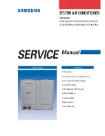
OPERATING & MAINTENANCE

MILLENNIUM


TM

CENTRIFUGAL LIQUID CHILLERS

Supersedes:  160.60-O1 (1296)

Form 160.60-O1 (1197)

MODEL YG & YB

(DESIGN LEVEL A)

YG

YB

WARNING

SYSTEM CONTAINS REFRIGERANT UNDER PRESSURE.

SERIOUS INJURY COULD RESULT IF PROPER PROCEDURES ARE NOT FOLLOWED WHEN

SERVICING SYSTEM. ALL SERVICE WORK SHALL BE PERFORMED BY A QUALIFIED SERVICE

TECHNICIAN IN ACCORDANCE WITH YORK INSTALLATION/OPERATION MANUAL.

28699A

Summary of Contents for MILLENNIUM YG Series

Page 1: ...1 1197 MODEL YG YB DESIGN LEVEL A YG YB WARNING SYSTEM CONTAINS REFRIGERANT UNDER PRESSURE SERIOUS INJURY COULD RESULT IF PROPER PROCEDURES ARE NOT FOLLOWED WHEN SERVICING SYSTEM ALL SERVICE WORK SHAL...

Page 2: ...e Clock PRV Prerotation Vane LWT Low Water Temperature HOT High Oil Temperature OP Oil Pressure LCWT LeavingChilledWaterTemp ECWT Entering Condensing Water Temp YB MC MC G4 G3406 A Model Design Level...

Page 3: ...top Switch 38 Programming the MicroComputer Control Center 27 Display Messages 38 Programming System Setpoints 27 System Shutdown Messages 40 Service Keys 32 Engine Related Display Messages 44 Automat...

Page 4: ...down Demand Setpoint 29 11 Keypad Programming Clock Setpoint 29 12 Keypad Programming Daily Schedule Setpoint 30 13 Keypad Programming Holiday Setpoint 31 14 Keypad Programming Remote Reset Temp Range...

Page 5: ...38 SYSTEM RUN VANES HOLDING 38 SYSTEM RUN LOW PRESSURE LIMIT IN EFFECT 38 SYSTEM RUN HIGH PRESSURE LIMIT IN EFFECT 39 SYSTEM RUN PRESS STATUS 39 WARNING COND OR EVAP TRANSDUCER ERROR 39 WARNING PRV PO...

Page 6: ...IL TEMP 41 MON XX XX AM HIGH OIL PRESSURE 41 MON XX XX AM FAULTY COND PRESSURE XDCR 41 MON XX XX AM FAULTY OIL PRESSURE XDCR 41 VANE MOTOR SWITCH OPEN 41 SYSTEM READY TO START PRESS STATUS 41 START SE...

Page 7: ...E COOLDOWN 44 MANUAL ENGINE CYCLING 44 COMPRESSOR ROTATION FAULT 44 COMPR COASTDN ENGINE SHTDN PRESS STATUS 44 DAY TIME COMPRESSOR ROTATION FAULT 44 WARNING ENGINE SERVICE TIME ELAPSED 44 SUN 12 00 AM...

Page 8: ...AFTER COOLER WATER TEMPERATURE 46 ENGINE FAULT 46 CLUTCH FAILURE 46 LOW ENGINE OIL PRESSURE 47 HIGH ENGINE JACKET TEMP 47 SURFACE SPEED CONTROL ACTIVE 47 SURFACE SPEED CONTROL NOT ACTIVE 47 HIGH ENGI...

Page 9: ...LLEDLEAVING XXX X F RETURN XXX X F Refrigerant Pressures EVAP XXXX X PSIG COND XXXX X PSIG Comp Oil Pressure OIL PRESSURE XXX X PSID Engine Data ENGINE OIL PRESSURE XXX X PSIG ENGINE MANIFOLD PRESSURE...

Page 10: ...CONTROLCENTER COMPRESSOR ACDISTRIBUTION PANEL OILSUMP CONDENSER COOLER SUCTION LINE DISCHARGE LINE FIG 1A MODEL YB GAS ENGINE DRIVE CHILLER YORK POWER PANEL YORK MICRO PANEL ENGINEJACKETWATER LOCATION...

Page 11: ...s designed for operation and protec LD02532 The chiller is controlled by a modern state of the art MicroComputer Control Center which monitors its operation The control center is programmed by the ope...

Page 12: ...ressure Shutdown Electronic Ignition System Shutdown Clutch Failure Shutdown Sensor Failure Shutdown consisting of 1 Low Oil Pressure Warning Switch Fail 2 Low Oil Pressure Shutdown Switch Fail 3 High...

Page 13: ...s the compres sor lubrication pump to run for two 2 minutes and allows the gearbox lubrication pump to run during the four 4 minute coastdown engine cooldown cycle When the safety occurrence failure h...

Page 14: ...trol switch in the EN GINE MAINTENANCE mode and turn the ENGINEMAINTENANCESPEEDCONTROL switch to the PURGE position 7 Turnthe ENGINEMAINTENANCECONTROL switch to the START RUN position and hold for fif...

Page 15: ...d Temp Alarm Safety Shutdowns include Low Engine Coolant Level Shutdown Low Gear Box Oil Pressure Shutdown High Gear Box Oil Temperature Shutdown Electronic Ignition System Shutdown High Drive Line Vi...

Page 16: ...arm Optional Safety Shutdowns include Low Engine Coolant Level Shutdown Low Gear Box Oil Pressure Shutdown High Gear Box Oil Temperature Shutdown Electronic Ignition System Shutdown Clutch Engage Fail...

Page 17: ...will be required to take whatever action may be required to correct the interference Additionally any electronic equipment can generate EMI electromagnetic interference which depending upon the instal...

Page 18: ...S keypad These setpoints can also be displayed on the 40 character al phanumeric display The system setpoints are CHILLED LIQUID TEMPERATURE LCWT ENGINE LOAD LIMIT PULLDOWN DEMAND LIMIT CLOCK TIME OF...

Page 19: ...of system setpoints 4 Remote allows remote start remote stop of com pressor and remote reset of LCWT and engine load limit COMPRESSOR START RUN STOP RESET SWITCH This 3 position rocker switch is used...

Page 20: ...offset value will be taken as 0 psi in this instance To Display ENGINE DATA Press the ENGINE DATA display key as described on page 19 to produce the following alphanumeric display message ENGINE OIL...

Page 21: ...sure value and engine speed value from the Engine Con trol Center The program inserts these values into a load profile graph as shown below to determine the engine loading Fig 6 shows graphs for each...

Page 22: ...0 30 00 25 00 20 00 15 00 5 00 0 00 10 00 Speed RPM Manifold Pressure PSIA Manifold Pressure vs Engine Speed G3508 Engine at Various Loads 45 00 0 Load 25 Load 50 Load 75 Load 100 Load 125 Load LD0253...

Page 23: ...t setpoint available to the Energy Man agement System EMS This chilled liquid temp value must also be entered into the EMS Further any subsequent change to this value must also be entered into the EMS...

Page 24: ...n the chilled liquid temp setpoint can be remotely re set over a range of 46 F to 56 F 46 10 56 If not programmed the default value for this parameter is 20 F For additional information on remote LCWT...

Page 25: ...ntil the DAILY SCHEDULE key is released or Press and release the DAILY SCHEDULE setpoint key Then press and release the DISPLAY HOLD key The chiller start and stop times for each day of the week are s...

Page 26: ...IMITY SENSOR POSITION 66 MILS PROXIMITY SENSOR REFERENCE 67 MILS HIGH SPEED DRAIN TEMPERATURE 126 1 F LEVEL CONTROL POSITION 20 LEVEL CONTROL SETPOINT 20 ENGINE SPEED 1647 RPM ENGINE RPMS TARGET 1640...

Page 27: ...code 9675 and proceed 6 This is displayed ACCESS TO PROGRAM KEY AUTHORIZED NOTE Unless terminated by pressing the ACCESS CODE key again the operator will have access to the PROGRAM key for 10 minutes...

Page 28: ...is value must be entered into the Energy Management System Refer to previous explanation or REMOTE RESET TEMP RANGE page 25 2 Use ENTRY keys to enter desired value 3 Press and release ENTER key This m...

Page 29: ...DOWN DEMAND SETPOINT To Enter CLOCK Setpoint Refer to Fig 11 1 AssureMicroBoardProgramjumperJ57isin CLKON position 2 Press and release CLOCK setpoint key The follow ing program prompt message is displ...

Page 30: ...M key to change AM to PM or vice versa d Use the ENTRY keys to enter desired hours and minutes stop time e If necessary press the AM PM key to change AM to PM or vice versa 3 Press the ADVANCE DAY SCR...

Page 31: ...form Step 1 press CANCEL key and then press ENTER key This message is displayed PROGRAM MODE SELECT SETPOINT To cancel one of the designated holidays perform Step 1 press ADVANCE DAY SCROLL key until...

Page 32: ...the refrigerant level ac tuator that is connected to the variable orifice to maintain the condenser refrigerant level to the setpoint level pro grammed into the MicroComputer Control Center by the fie...

Page 33: ...vane motor switch closed the output to the level control is opposite of the output to the vane motor If a close signal is being applied to the vane motor an open signal will be applied to the level co...

Page 34: ...SYSTEM RUN LEVEL VALVE CLOSING is displayed when a close command is given FIXED POSITION OPERATION It might be necessary to operate the chiller with the vari able orifice in a fixed position This coul...

Page 35: ...osing of the vanes is indicated on the display When the vanes are opening this mes sage is displayed SYSTEM RUN VANES OPENING If the vanes are closing this message is displayed SYSTEM RUN VANES CLOSIN...

Page 36: ...ce mechanic Improper settings may cause severe damage to the unit VANE SPEED TOGGLE SERVICE KEYS CONTROL VANE POSITION This key will allow you to select whether keys control speed or vane position HIS...

Page 37: ...this is displayed SERVICE MODE To change operating mode proceed as follows 1 Press ACCESS CODE key 2 This message appears ENTER VALID ACCESS CODE 3 Using Entry keys enter 9 6 7 5 4 As each digit is e...

Page 38: ...is in REMOTE mode To STOP compressor Move switch from RUN to STOP RESET position This will initiate a standard shutdown which takes sev eral minutes to complete To RESET Control Center Following a saf...

Page 39: ...ill appear when the RTC battery fails To correct this message you must press STATUS and the following message will be displayed REPLACE RTC U16 REPROGRAM SETPOINTS Install a good RTC and reprogram set...

Page 40: ...ard must be removed for a brine unit MON XX XX AM FLOW SWITCH Chiller had a quick shutdown because a chilled liquid flow switch has opened The flow switch must open for a minimum of 2 seconds in order...

Page 41: ...generally indicative of a defective condenser transducer or the transducer has been disconnected After the prob lem has been corrected the chiller can be restarted Safety shutdown reset procedure req...

Page 42: ...er could result in severe compressor damage In addition to 160 60 M1 procedures the safety shut down reset procedure page 14 is required FAULTY PROXIMITY PROBE The chiller has shutdown because the PRO...

Page 43: ...will be maintained If this message appears the RTC IC chip U16 on the Micro Board must be replaced If there had been a power failure while this message is displayed the setpoints will have been lost...

Page 44: ...ntinuously WARNING COMPRESSOR SERVICE TIME ELAPSED This message has a range of 750 hours to 9900 hours with a default value of 750 hours which can be set by the operator COMPR COASTDOWN ENGINE COOLDOW...

Page 45: ...60 This display is showing you the min max default values of the engine vibration The panel stores a programmable safety cutout level for the sensor This cutout level deter mines when the chiller iss...

Page 46: ...ies 1750 RPM for 3500 series 1167 RPM for 3600 series ENGINE OVERLOAD The chiller had a quick shutdown because the Micro Panel detected continuous operation at greater than 110 load for 30 seconds Saf...

Page 47: ...become active the following message will be displayed as a scrolled message under the hidden key SURFACE SPEED CONTROL NOT ACTIVE These messages are also shown on the standard history printout in acco...

Page 48: ...er is started Refer to Section 2 Prior to start the clock must be programmed for the proper day and time Any setpoints which are desired to be changed may be programmed If not programmed the default v...

Page 49: ...s sent to the Engine Control Panel ECP Condenser water pump contacts are closed 9 If clutch engagement is detected by clutch pressure switch closure speed is ramped from idle to full speed approximate...

Page 50: ...mpdown would normally start However a coastdown will occur for all shutdowns The message displayed during the coastdown period shows COMPRESSOR COASTDOWN ENGINE SHUTDOWN The engine rampdown time is de...

Page 51: ...TEMP X LWT DEG F DEG C TEMP SETPOINT SETPOINT WHEN THESETPOINTISRAISED LWT 36 2 2 FOR 10 MINUTES BELOW LCWT 40 4 4 LWT 36 2 2 X LWT DEG F DEG C CHILLEDLIQUID LWT 4 2 2 BELOW THE TEMP SETPOINT CHILLED...

Page 52: ...lower than the value determined by referring to the formula below Min ECWT LCHWT C RANGE 5 15 x LOAD 100 where ECWT entering condensing water temperature LCHWT leaving chilled water temperature C RAN...

Page 53: ...ecessary 1 Drain and replace the oil in the compressor oil sump See Oil Charging Procedure page 61 2 Cooler and Condenser a Inspect and clean facility water strainers b Inspect and clean tubes as requ...

Page 54: ...ilpump The actualwaterpumpcontactoperationisdependentupon the position of Micro Board Jumper J54 3 Opentheswitchtothecoolingtowerfanmotors ifused 4 The compressor sump oil heater thermostically con tr...

Page 55: ...T 4 SECTION 4 YG YB SYSTEM COMPONENTS DESCRIPTION 27704A GAS ENGINE DISCHARGELINE SUCTIONLINE COOLER CONDENSER OILSUMP AC DISTRIBUTION PANEL COMPRESSOR YORKMICROCOMPUTER CONTROL PANEL ENGINE CONTROL...

Page 56: ...POWER PANEL YORK MICRO PANEL ENGINEJACKETWATER LOCATIONWHENINSTALLED CATERPILLAR CONTROL PANEL 1T 3KVA TRANSFORMER BATTERY CHARGER RT4 LEAVING COND WATER SENSOR RT5ENTERING COND WATER SENSOR RT9ENTER...

Page 57: ...in Compressor a Meshing surfaces of drive and pinion gear teeth GENERAL YG Models The YG Millennium Gas Engine Drive Chiller ships as two packages a shell package and a drive line package The shell p...

Page 58: ...erature is lowered the amount of refrigerant absorbed will be increased If the quantity of refrigerant in the oil becomes excessive violent oil foaming will result as the pressure within the system is...

Page 59: ...re within 20 below the programmable cutout level for five seconds continuously the panel will issue a warning indication and the message WARNING HIGH ENGINE VIBRATION DETECTED will be displayed when t...

Page 60: ...h shall be connected to J7 Pin 1 on the I O Expansion Board LD02316 LD02219 LD02220 PHYSICAL LOCATION OF THE TEMPERATURE SWITCH Once the vibration level is set if at any time the vibration readings ar...

Page 61: ...l keep the concentration of refrigerant in the oil to a minimum When the oil reservoir is initially charged with oil the oil pump should be started manually to fill the lines pas sages oil cooler and...

Page 62: ...0 AM Low Oil Manual Low Oil Pressure 25 PSID 15 PSID Pressure Transducer OP MON 10 00 AM High Pressure Manual High Pressure 180 PSIG R 134A 120 PSIG R 134A Safety Control HP MON 10 00 AM Evap Trans Ma...

Page 63: ...ual reset of ECP required To restart press compressor switch from STOP RESET Defective Evap Pressure Transducer or Leaving to START position Manual reset of ECP required Chiller Water thermistor RS1 L...

Page 64: ...er than normal with normal discharge temperature Temperature of chilled water too low with Insufficient load for system capacity Check prerotation vane motor operation low engine load and setting of l...

Page 65: ...re display key drops to 70 of oil pressure when compressor was Extreme bearing wear Inspect compressor originally started 9 SYMPTOM OIL RETURN SYSTEM CEASES TO RETURN AN OIL REFRIGERANT SAMPLE Oil ref...

Page 66: ...it able vacuum on the system Operation Dehydration of a refrigeration system can be obtained by this method because the water present in the system re acts much as a refrigerant would By pulling down...

Page 67: ...is dependent on the size or volume of the system the capacity and efficiency of the vacuum pump the room temperature and the quantity of water present in the system By the use of the vacuum indicator...

Page 68: ...ntil the system pressure is raised above the point corresponding to the freeze point of the cooler liquid For water the refrigerant pressure corresponding to the freezing point is 30 PSIG for R134a at...

Page 69: ...which finds its way into the tubes and accumulates there This material usually does not build up on the inner tube surfaces as scale but does interfere with heat transfer Rust or sludge can gener ally...

Page 70: ...men working at both ends of the cooler carefully test each tube one man re moving corks at one end and the other at the oppo site end to remove corks and handle the leak detec tor Start with the top r...

Page 71: ...towers closed wa ter systems etc frequently results in one or more of the following 1 Scale Formation 2 Corrosion or Rusting 3 Slime and Algae Formation It is therefore to the benefit of the user to...

Page 72: ...Olympic Team 36USC380 P O Box 1592 York Pennsylvania USA 17405 1592 Subject to change without notice Printed in USA Copyright by York International Corporation 1997 ALL RIGHTS RESERVED Form 160 60 O1...

Reviews: