background image

2009.10.30

Summary of Contents for Factory B-MAX4

Page 1: ...2009 10 30 ...

Page 2: ...ving drivetrain components Make sure that all wires are properly connected to prevent shorting Unnecessary modifications may be unsafe and hinder performance Always paint in a well ventilated area away from flames PRECAUTIONS BEFORE RUNNING Yokomo R C cars are built for competition use and some models may exceed speeds of 40km per hour Practice common sense and run the car in open safe places or R C...

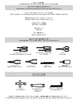
Page 3: ... WRENCH 六角レンチ 1 5 2 0 ALLEN WRENCH 性能を十分に発揮させる為にイラス トをしっかり参照し 説明書の順番に従って確実に組み上げて下さい For assembly follow the figures and the instructions closely so that your machine will perform at its best ニッパー SIDE CUTTER カッター HOBBY KNIFE 瞬間接着剤 QUICK DRYING GLUE ラジオペンチ NEEDLE NOSE PLIERS 組み立ての際に別途用意する工具 ASSEMBLING TOOLS REQUIRED NOT INCLUDED IN KIT ボックスレンチ 7 0 5 0 NUT DRIVER ハサミ SCISSORS プラス ドライバー 大 小 SCREW DRIV...

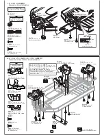
Page 4: ...Front Transmission Case Lower BM 302R リヤミッションケース ロア 1 Rear Transmission Case Lower BM 302C センターミッションケース ロア 1 Center Transmission Case Lower BM 304SS スペシャルモーターマウント 1 Special Motor Mount BM 300 M3x10 サラタッピング FH Tapping Screw 向きに注意 Note position BM 300 リヤサスマウント F Rear Suspension Mount F 広い方を下に Wider area on bottom 広い Wide 狭い Narrow BM 300 M3x8 ナベタッピング 4 BH Tapping Screw BM 300 M3x10 サラタッピング 2 FH Tapp...

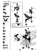
Page 5: ...ッドエンドボール M 3 Ball Stud M BM 200H スプリング 1 Spring BM 200 サーボセイバー 上 1 Servo Saver Top BM 200 サーボセイバー 下 1 Servo Saver Bottom BM 200 サーボセイバー L 1 Servo Saver Left BM 200H サーボセイバーナット 1 Servo Saver Nut BM 200H ワッシャー 1 Washer 袋 3 の内容 Bag 3 Contents 5 サーボセイバーナット は右記の寸法までねじ 込みます Screw on the servo saver nut to the measurement shown on the right 十字レンチ等の工具類は袋 18 のホイルの方に入っております The cross wrench and other tools ...

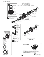
Page 6: ...ack grease スラストボールには必ずブラックグリスを 塗布してください Oリング部にも塗布することで防塵効果が得 られます Apply a liberal amount of black grease to the diff thrust balls Applying it to the O ring will help prevent dust from entering ZS 507 スラストワッシャー Thrust Washer ZS 507 スラストボール 8個 Thrust Ball 8 Pcs ZS 507 スラストワッシャー Thrust Washer BM 508 デフスクリュー Diff Screw BM 508 O リング O Ring 切りかきを合わせる Key onto the diff joint 切りかきを合わせる Key onto the diff joint...

Page 7: ...Input Shaft BM 010CFB センターボーン フロント L Center Bone Front Long BM 010CRB センターボーン リヤ S Center Bone Rear Short BM 010TP カップジョイント Cup Joint BM 010TP ジョイントピン Joint Pin BM 010TP M3x2 5 セットスクリュー Set Screw 1 5 メインドライブシャフトの組み立て方 Main Drive Shaft Assembly Installation メインドライブシャフトは組立て済みです 分解 組立ての際に参照下さい The Main Drive Shaft comes pre assembled Please see below for disassembly assembly instructions CS BG ブラックグリ...

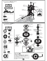
Page 8: ... the main drive cup BM 670P スリッパーメインプレート Slipper Main Plate BM 670C スリッパーパッド Slipper Pad BM 670C スリッパーパッド Slipper Pad BM SG87 スパーギヤ 87T Spur Gear 切りかきをピンに合わせる Key onto the drive pin ドライブカップ先端の切りかきがメイン プレートとドライブピンに合っているか確 認しながら M3x8ビスを締め込みます Line up the drive cup slot with the main plate and drive pin and then tighten the M3x8 screw スリッパーナットは一番緩めた状態から 1 回転と 1 2 締め込みます 実走行でのスリッパー調整はゼロ発進時にわずかに滑る程度が目安...

Page 9: ...3 M3x12 ナベタッピング BH Tapping Screw BM 203 M2 6x8 トラスタッピング BH Tapping Screw BM 203 ボディポスト Body Post BM 003 M3x12 ナベタッピング BH Tapping Screw BM 302C M3x15 ナベビス BH Screw BM 302C M3x25 ナベタッピング BH Tapping Screw BM 302GC アルミ製メインギヤカバー Alminum Main Gear Cover CS BG ブラックグリス 黒 を塗布します Apply a black grease アッパーデッキはボディポストを取り付けてから組み込みます Before installing the Upper Deck attach the Body Posts 向きに注意 Note position BM 3...

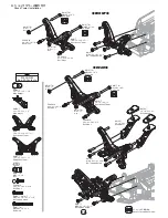
Page 10: ... ウイングマウント 2 Wing Mount BM 001 ウイングスペーサー 2 Wing Spacer BM 017 フロントショックタワー 1 Front Shock Tower FRONT REAR BM 017 M3x12 ナベタッピング BH Tapping Screw BM 017 M3x12 ナベタッピング BH Tapping Screw ZC 206LH ロッドエンドボール L Ball Stud L BM 017M M3 ナット Nut BM 017M M3x25 ナベビス BH Screw BM 017 リヤショックタワー Rear Shock Tower BM 017M M3x25 ナベビス BH Screw BM 017M M3 ナット Nut ZC 206LH ロッドエンドボール L Ball Stud L ZC 206LH ロッドエンドボール L Ball ...

Page 11: ......

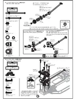
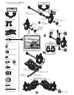
Page 12: ...earing BM 009A M2 6x5 トラスタッピング 2 BH Tapping Screw BM 011S ホイルスペーサー 2 Wheel Spacer BM 010BC リヤ ベアリングカラー 青 2 Rear Bearing Collar Blue BM 415C ハブキャリアスペーサー 黒 4 Hub Carrier Spacer Black BM 011 ホイルハブピン 2 Wheel Hub Pin ZC S50S φ5 シム 4 Shim BM 009A アウターサスアームピン 2 Outer Suspension Arm Pin 12 ユニバーサルドライブシャフトは組立て済みです 分解 組立ての際に参照下さい The Universal Drive Shafts come pre assembled Please see below for disassembly ...

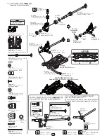
Page 13: ...300 M3x10 サラタッピング 2 FH Tapping Screw BM 009B インナーサスアームピン S 2 Inner Sus Arm Pin Short BM 001 M3x8 サラタッピング 2 FH Tapping Screw BM 300 ブレースブッシュ 2 Brace Bushing 袋 12 の内容 Bag 12 Contents FRONT REAR BM 300F M3x10 ナベタッピング 2 BH Tapping Screw BM 009B インナーサスアームピン S Inner Sus Arm Pin Short BM 009B インナーサスアームピン S Inner Sus Arm Pin Short BM 300FB スペシャルフロントブレース Special Front Brace BM 300 ブレースブッシュ Brace Bushing BM...

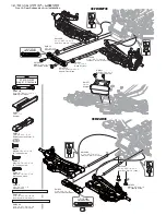
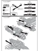
Page 14: ...mm Titanium Turnbuckle 片方が逆ネジになっています One side is reverse threaded BM TBL ターンバックルレンチ Turnbuckle Wrench フロント アッパーロッド Front Upper Rod フロント アッパーロッド Front Upper Rod ステアリングロッド Steering Rod ステアリングロッド Steering Rod サーボロッド Servo Rod 14 袋 13 の内容 Bag 13 Contents P 15 で使用します Used on P 15 BM 206 ショックエンド 4 Shock End BM 206 ロッドエンド 14 Ball Cup ZC TB39 39mm チタンターンバックル 7 39mm Titanium Turnbuckle リヤアッパーロッド Rear Upper...

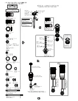
Page 15: ...k Cap BM S4R12 リヤショックボディ 2 Rear Shock Body BM S106 ピストン 黒 2 Piston Black BM S116 ピストン 白 2 Piston White BM S4AJ12 アジャストナット 4 Adjusting Nut YS 4C 8 O リング φ9 4 O Ring BM S4AJ12 O リング φ14 4 O Ring YS 7 2 カラー 白 4 Collar White YS 7 2 カラー 黒 4 Collar Black YS 7 2 C クリップ 4 C Clip BM S4AJ12 O リング φ14 O Ring BM S4AJ12 アジャストナット Adjusting Nut BM S4F12 フロントショックボディ Front Shock Body BM S4R12 リヤショックボディ Rear Shock ...

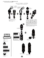
Page 16: ... 1mm 程度浮かせ た位置で止め エアが抜けるように傾けてゆっくりとシャフ トを押し上げます 一杯まで押し上げたらショックキャップ をしっかりと締め込み 溢れた余分なオイルを拭き取ります ショックキャップを締め込んでシャフトが最後まで入らない 場合は再度キャップを緩めてオイルを抜いてください Tighten the shock cap to where it is 1mm from being fully tightened Slowly push up the shaft to release the air inside Once the shaft is pushed all the way up securely tighten the shock cap Wipe away any excess oil If you are unable to insert the shaft...

Page 17: ...プボール Aluminum Shock Cap Ball リヤショック Assy Rear Shock Assembly フロントショック Assy Front Shock Assembly FRONT REAR 17 BM 17M M3 ナイロンナット Nylon Nut BM 17M M3 ナイロンナット Nylon Nut YS 8BH アルミ製ショックキャップボール Aluminum Shock Cap Ball YS 8BH アルミ製ショックキャップボール 4 Aluminum Shock Cap Ball M3x15 ナベビス 4 BH Screw M3x15 ナベビス BH Screw M3x15 ナベビス BH Screw M3x15 ナベビス BH Screw M3x15 ナベビス BH Screw ...

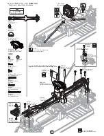
Page 18: ...使用下さい センターシャフトにコードが干渉する恐れがあるため シャシー中央の内側は必ず貼ってください Apply the foam tape thick to the dotted area To prevent the wires from rubbing against the center shaft always apply along the inside of the center of the chassis BM BP バッテリーパッド Battery Pad BM BP バッテリーパッド Battery Pad BM 118G M3x15 サラビス 4 FH Screw BM 118G バッテリープレート Battery Plate BM 118G M3x15 サラビス FH Screw SD 011R O リング 黒 O Ring Black BM 118G マウントナ...

Page 19: ... the gears to strip Please adjust the gear mesh carefully as insufficient clearance between the teeth will cause excessive gear noise as well as causing a drag in the drivetrain 0 3 m m タッピングビス使用禁止 Do not use tapping screws 1 5 六角レンチ 1 5mm Allen Key 1 5mm 19 BM 304SS M3x18 ナベビス BH Screw BM 304SS M3x6 ナベビス 2 BH Screw BM 304SS M3x12 ナベビス 1 BH Screw BM 4818 M3x3 セットスクリュー 1 Set Screw BM 4818 18T ピニオンギヤ ...

Page 20: ...ed Tape BM 203 M3x8 サラタッピング FH Tapping Screw ZR 200A アンテナパイプ Antenna Tube ZR 200C アンテナキャップ Antenna Cap BM 203 アンテナマウント Antenna Mount アンテナ線 Antenna Wire アンテナパイプをアンテナマウントに しっかり差し込んでからパイプ先端か ら出ている線とパイプにアンテナキャ ップを被せます Once the antenna tube has been securely inserted into the antenna mount place the antenna cap over the protruding wire and antenna tube アンテナを取り付ける際は アンテナ線をアン テナマウント アンテナパイプ順に通します When in...

Page 21: ...ロントタイヤ Front Tire フロント用 リヤ用各 2 セット作ります Assemble 2 Front and 2 rear フロントタイヤ Assy Front Tire Assembly リヤタイヤ Assy Rear Tire Assembly タイヤのサイドをめくり ホイルとの隙間に瞬間接着剤を 流し込み 両サイドを接着します Pull the sidewall of the tire slightly away form the rim and apply CA Cyanoacrylate glue in between the tire bead and rim 瞬間接着剤 別途ご用意下さい CA Cyanoacrylate glue sold separately BM N4F M4 ナイロンナット Nylon Nut BM N4F M4 ナイロンナット Nylon ...

Page 22: ...エンドキャップ Closed Ball End ZC 206A アンチロールバーボール Anti Roll bar ZC SS312 M3x12 セットスクリュー Set Screw ZC SS34 M3x4 セットスクリュー Set Screw スタビホルダー Sway Bar Holder 締め過ぎ注意 Do not over tighten BM 412 スタビライザー 1 1 Sway Bar ZC 206A M3x3 セットスクリュー Set Screw M3x4 セットスクリューはスタビライザーが ガタなくスムーズに動くように調整してください Adjust the M3x4 Set Screws to remove any play but allow the sway bar to swivel smoothly 22 ボディ ウイングのカット Body and Wing C...

Page 23: ...ntenna φ5mm ボディポスト Body post φ5mm ウイングマウント Wing mount BM 101 B MAX4 ボディ 1 B MAX4 Body カットラインに沿ってカットします Cut along the cutting line カットラインに沿ってカットします Cut along the cutting line 23 ボディ加工のおすすめアイテム カットには YT CS2 曲線バサミ 1200 穴あけには YT BMR ボディリーマー 2800 Recommended items for preparing the body YT CS2 Curved Scissors for cutting YT BMR Body Reamer for opening holes ...

Page 24: ...ます その際にマスキングシートがボディに密着していないとにじみの原因になるの で注意してください 塗料はポリカーボネイト専用 パクトラ製カラースプレーなど を使用してください スプレー塗料は1回で厚塗りしてしまうと塗料がたれたり 塗りムラができるので 全体に 薄く塗って乾かし2 3回に分けて塗装するようにしてください ボディ表面の保護シートは塗装後に剥がすようにしてください Painting the body Wash the inside of the body with luke warm water and a mild soap or detergent such as liquid dishwashing soap prior to painting Oil residue or dust will prevent the paint from adhering to the p...

Page 25: ...用するパーツ Parts used on this page RC 313S フードピン 3 Body Clip ZC 105 マジックテープ 各 1 Velcro Tape One of each RC 313S フードピン Body Clip RC 313S フードピン Body Clip ZC 105 マジックテープ Velcro Tape ZC 105 マジックテープ Velcro Tape ZC 105 マジックテープ Velcro Tape RC 313S フードピン Body Clip 25 反対側にも同様にボディ内側に貼ります For the opposite side apply in the same manner to the inside of the body ...

Page 26: ...joint and diff screw and insert the 2mm allen key to lock the diff joint and diff screw レンチで固定した方と反対側のタイヤを矢印方向に回すと締まります デフジョイントの移動量を確認しながらタイヤを回す際は少しずつ慎重に With the wrench locked on one side rotate the opposite side tire in the direction of the arrow to tighten Turn the tire in small increments while closely monitoring the amount of movement of the diff joint この作業はデフ単体で調整するより力が掛かり易いため デフリングやデフボール等を傷める恐れ...

Page 27: ...losely monitoring the amount of movement of the drive cup 27 ドライブカップを矢印方向に回すと締まります ドライブカップのスリットを基準に 1mm 程度 ずつ回してスリッパーの滑り具合をチェックし てください Rotating the drive cup in the direction of the arrow will tighten the slipper Using the slit as a mark turn the cup in 1mm increments while checking the amount of slippage each time 2mm アレンキーをスリッパーナットの溝に差し込みナットを固定します Insert the 2mm allen key into the groove located...

Page 28: ... 105 2 ZC S50S BM 415C BM 009A BM 017M BM 300FB BM 300 BM 009A BM 017M BM 009B BM 008F BM 415C BM 413 ZC S50S BB 105 2 BM 414 BM 415S BM 011 BM 011S ZC S50S BB 105 2 BM 010BC BM 414 ZC 206MH ZC 206MH BM 414 ZC 206MH ZC 206MH BM 010F BM 010F BM 008F BM 413 BM N4F BM 414 BB 730 4 BM 202R BM 200 BM 200H BM 200L BM 010CF BM 504 SD 303S ZC S80S BB 1480 2 BB 105 2 BB 730 4 BM 200H ZC 206MH ZC 206MH BM 2...

Page 29: ... SD TB39 BB 105 2 ZC S50S ZC S50S BB 105 2 BM 010BC BM 415R0 BM 011S BM 011 BM 415C BM 302R BM 302R BM 203 BM 001 BM 001 ZC 206LH BM 017 BM 017M YS 8BH BM 017 BM 203 ZR 200A BM 203 BM 203 BM 203 BM 203 BM 200 ZC 206MH BM 206 BM 206 SD TB39 BM 002 BM 302R BM BP BM 011 BB 1812 BM 508T ZC S120S BM 508 ZS 507 BM 508 BM 501 ZS 506 BB 85 4 BM 501 BM 503 ZD 505 BB 85 4 ZS 506 BB 1812 ZC S120S BM N4F BM N...

Page 30: ... Ver 03 DIFF ONE WAY 1 2 3 4 OIL 300 350 20 mm mm BLACK S M L DRIVE 87T LOCK 18T 2 35 MOTOR BRUSHES BATTERY ESC NOSRAM PEARL evo ISTC F RONT TIRE INSERTS WHEELS R EAR TIRE INSERTS WHEELS TOE IN OUT 1 T 21 2 2 23 TIRE mm x FULL RIP SPUR PINION mm T Bonded Sintered mm SPRING 1 2 3 4 OIL 250 300 28 mm mm BLACK ORANGE mm x 1 0 1 1 1 2 1 3 1 4 1 0 1 1 1 2 1 3 1 4 X SHOCK X SHOCK 1 mm 2 BLACK WHITE ...

Page 31: ...IRCUIT COMMENT Ver 03 DIFF ONE WAY 1 2 3 4 OIL mm mm BLACK S M L DRIVE 87T LOCK 18T 2 35 MOTOR BRUSHES BATTERY ESC NOSRAM PEARL evo ISTC F RONT TIRE INSERTS WHEELS R EAR TIRE INSERTS WHEELS TOE IN OUT T TIRE mm x FULL RIP SPUR PINION mm T Bonded Sintered mm SPRING 1 2 3 4 OIL mm mm BLACK mm x 1 0 1 1 1 2 1 3 1 4 1 0 1 1 1 2 1 3 1 4 X SHOCK X SHOCK mm ...

Page 32: ......

Reviews: