


YASKAWA Europe
TOEP C710606 101A - V1000 MMD IP65 Motor Mounted Drive - Quick Start Guide
EN 1
ENGLISH
Quick Start Guide
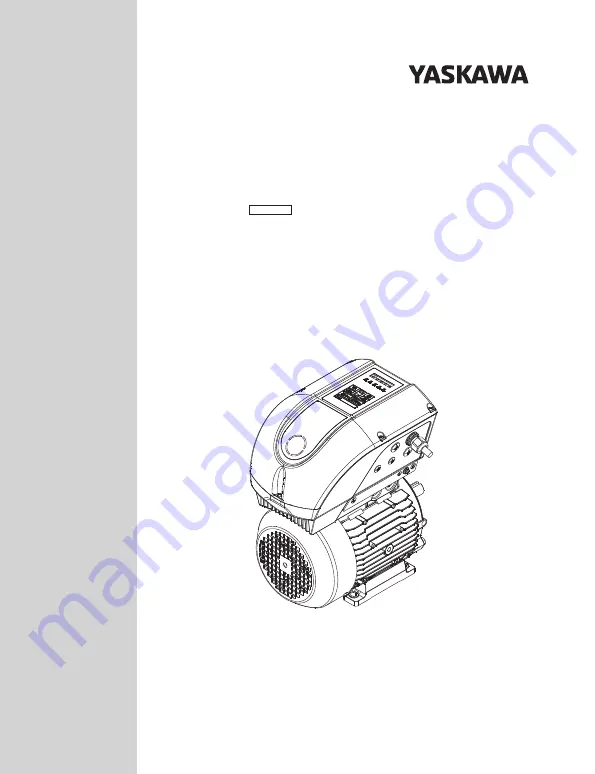
YASKAWA V1000 MMD
IP65 Motor Mounted Drive
Models:
400 V Class, Three-Phase Input: 1.5 to 5.5 kW
MANUAL NO. TOEP C710606 101A
Type:
SP-V1M
To properly use the product, read this manual thoroughly
and retain for easy reference, inspection, and maintenance.
Ensure the end user receives this manual.
The V1000 drive in this package is equipped with a special firmware
to operate permanent magnet motors.
1
2
3
4
5
6
7
8
WWW.NNC.IR


