background image

CONTENTS

SPECIFICATIONS ...................................................................................... 3

PANEL  LAYOUT ....................................................................................... 4

CIRCUIT  BOARD  LAYOUT ....................................................................... 5

BLOCK  DIAGRAM .................................................................................... 6

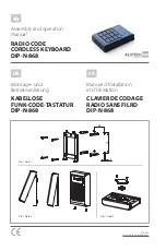
DISASSEMBLY  PROCEDURE ................................................................. 7

LSI  PIN  DESCRIPTION .......................................................................... 12

IC  BLOCK  DIAGRAM ............................................................................. 14

CIRCUIT  BOARDS .................................................................................. 15

TEST  PROGRAM & INITIALIZE ............................................................... 17

PANEL VOICE LIST ................................................................................. 19

GM VOICE LIST ....................................................................................... 20

STYLE LIST ............................................................................................. 21

MIDI  IMPLEMENTATION  CHART ............................................................ 22

PARTS  LIST

PANEL SWITCH TABLE

OVERALL  CIRCUIT  DIAGRAM

SERVICE MANUAL

PK   001617

HAMAMATSU,JAPAN

1.95K-504   I   Printed in Japan’99.03

Summary of Contents for PortaTone PSR-270

Page 1: ...RE 7 LSI PIN DESCRIPTION 12 IC BLOCK DIAGRAM 14 CIRCUIT BOARDS 15 TEST PROGRAM INITIALIZE 17 PANEL VOICE LIST 19 GM VOICE LIST 20 STYLE LIST 21 MIDI IMPLEMENTATION CHART 22 PARTS LIST PANEL SWITCH TABLE OVERALL CIRCUIT DIAGRAM SERVICE MANUAL PK 001617 HAMAMATSU JAPAN 1 95K 504 I Printed in Japan 99 03 ...

Page 2: ...pecification sre subject to change without notice or obligation to retrofit Should any discrepancy appear to exist please contact the distributor s Service Division WARNING Static discharges can destroy expensive components Discharge any static electricity your body may have accumulated by grounding yourself to the ground buss in the unit heavy gauge black wires connect to this buss IMPORTANT Turn...

Page 3: ...us 4 types DSP 33 types Harmony 26 types Song 3 Preset Songs Demo 3 User Songs SongClear Recording Song User Song 3 Songs RealTimeRecording StepRecording Recording Tracks 1 2 3 4 5 6 CHORD EZChord 8 Banks Bank Chain OTS One Touch Setting User 4 Setups x 4 Banks MIDI TransmitSettings Receive Settings Local Control Clock BulkSend Receive InitialSend Auxiliary jacks PHONES OUTPUT DCIN10 12V MIDIIN OU...

Page 4: ... 12 START STOP button 13 INTRO ENDINGbutton 14 MAIN A B AUTO FILL buttons 15 CHORD GUIDE button 16 RECORD button 17 ONE TOUCH SETTING SONG MEMORY but tons 18 HARMONYbutton 19 REVERB button 20 DUAL button 21 TOUCHbutton 22 Power switch STANDBY ON 23 DEMO button 24 DC IN 10 12V jack 25 PHONES OUTPUT jack 26 FOOT SWITCH jack 27 MIDI IN OUT terminals Control Panel Rear Panel PHONES OUTPUT DC IN 10 12V...

Page 5: ...L270 PVS W0805 AM PN CN701 AM PN CN702 AM PN 9P L160 AM PN W0704 AM PN GND EARTH GND 1P 380 AM PN W0903 AM PN CN802 SPEAKER L SP L 2P 230 AM PN W0803 AM PN CN903 BATTERY BATT 2P L380 510 450 AM PN CN803 SPEAKER R SP R 2P 600 AM PN W0802 MKS3 CN1 DM CN102 DM MKS 6P 220 440 MKS3 CN2 MK L 160d 12P 190 160d AM PN CN703 DM CN702 PN SW 16P L120 AM PN W0703 MK H MK L MK B 12P 215 160e AM PN CN602 DM CN60...

Page 6: ...PSR 270 6 28CA1 8813220 ...

Page 7: ...wer case assembly See Procedure 1 2 2 Remove the four 4 screws marked 330 The DM circuit board with the shield box can then be re moved Fig 2 2 3 Remove the ten 10 screws marked 310 The DM circuit board can then be removed Fig 2 3 INV Circuit Board 3 1 Remove the lower case assembly See Procedure 1 3 3 Remove the two 2 screws marked 320 The INV circuit board can then be removed Fig 2 4 Keyboard As...

Page 8: ...he knob can then be removed Fig 4 6 3 Pull the knob off the PSV 2 3 circuit board 7 PVS 1 3 Circuit Board 7 1 Remove the lower case assembly See Procedure 1 7 2 Remove the DM circuit board with the shield box See Procedure 2 7 3 Removethefour 4 screwsmarked 320C ThePSV 1 3 circuit board can then be removed Fig 4 8 AMPN 1 2 Circuit Board 8 1 Remove the lower case assembly See Procedure 1 8 2 Remove...

Page 9: ...ontacts Be careful not to touch the conductive surface The LCD can then be removed Fig 5 10 1 Remove the lower case assembly See Procedure 1 10 2 Remove the INV circuit board See Procedure 3 10 3 Remove the PSV 2 3 circuit board See Proce dure 6 10 4 Remove the EL light When replacing the EL light solder the wires to the EL light leads within 3 seconds a wire keep ing the leads more than 3 mm Do n...

Page 10: ...bly 12 1 Remove the keyboard assembly See Procedure 1 12 2 Remove the two 2 screws marked 30 The MKS3 circuit board can then be removed Fig 7 12 3 Remove the MK circuit board while pressing the fifteen 15 hooks A inward and then remove the rubber contact Fig 8 12 4 Remove the twenty one 21 screws marked 140 12 5 Remove the black keys from the lower notes Af terwards remove the white keys DFA and C...

Page 11: ...s install the black keys from the higher notes and tighten the twenty one 21 screws marked 140 Fig 9 13 2 Install the rubber contacts in the assembly while pressing the keys as shown in Figure 10 Check that the rubber contact has been firmly placed into position in the area indicated by the arrow in Fig ure 11 Fig 10 11 and 12 When fitting the rubber contacts raise both ends of the frame so that t...

Page 12: ...O 41 DB2 I O 2 S21 O 42 DB3 I O 3 S20 O 43 DB4 I O Data interface 4 S19 O 44 DB5 I O 5 S18 O 45 DB6 I O 6 S17 O 46 DB7 I O 7 S16 O 47 C1 O 8 S15 O 48 C2 O 9 S14 O 49 C3 O 10 S13 O 50 C4 O 11 S12 O Segment signal output for LCD 51 C5 O 12 S11 O driving 52 C6 O 13 S10 O 53 C7 O 14 S9 O 54 C8 O Common signal output for LCD 15 S8 O 55 C9 O driving 16 S7 O 56 C10 O 17 S6 O 57 C11 O 18 S5 O 58 C12 O 19 ...

Page 13: ...emory data bus 123 CMD0 I O Program memory Data bus 40 SMD15 I O Wave memory data bus 124 CMA21 O Program address bus 41 SOE O read signal 125 PDT15 I O SWX access data bus 42 SWE O write signal 126 PDT14 I O SWX access data bus 43 SRAS O RAS signal 127 PDT13 I O SWX access data bus 44 SCAS O CAS signal 128 PDT12 I O SWX access data bus 45 REFRESH O REFRESH signal 129 PDT11 I O SWX access data bus...

Page 14: ...PSR 270 14 ...

Page 15: ... Board Component side Patternside Note See parts list for details of circuit board component parts to MKS3 CN1 to AM PN1 2 CN602 to AM PN 1 2 CN703 to PSV 3 3 CN805 to AM PN 1 2 CN901 to MK L MKS3 Circuit Board to MK L to MK H to DM CN102 ...

Page 16: ...ND BY ON MASTER VOLUME INV Circuit Board to SPEAKERS R FOOT SWITCH IN OUT MIDI to DM CN601 to DM CN702 PHONES AUX OUT DC IN 10 12V to BATTERY to SPEAKERS L to AM PN 1 2 CN701 to EL LIGHT to AMPN CN704 to AMPN 2 2 CN702 to AM PN CN907 to AMPN CN902 to DM CN501 to AM PN CN801 to PSV CN705 to DM CN101 to PSV 3 3 CN804 to PSV 2 3 CN904 to INV CN906 AMPN 2NA V206360 PSV 2NA V348100 INV 2NA V348100 AM P...

Page 17: ...ernately on the LCD 2 002 Rom Chk1 Checks the ROM The test result appears on the LCD 3 003 Ram Chk1 Checks all the RAMs which are connected to the CPU The test result appears on the LCD 11 011 TG1 Chk Outputs the sine wave by changing the channels in sequence from C2 to G4 After autoscaling is finished individual keys can be played If playing two or more keys simulaneously the final depressed key ...

Page 18: ...STAND BY ON switch on by normal mode during standing by If this should happen RAM data will be lost 47 047 Factory All RAMs are initialized and set to the factory preset date when executing this test The result appears on the LCD 48 048 TestExit Exit from the test program after executing this test 2 INITIALIZE Except for the data listed below all PSR 270 panel settings are reset to their initial s...

Page 19: ... Dance Kit 108 127 0 32 Jazz Kit 109 127 0 40 Brush Kit 110 127 0 48 Symphony Kit PIANO 001 0 112 0 Grand Piano 002 0 112 1 Bright Piano 003 0 112 3 Honky tonk Piano 004 0 112 4 Funky Electric Piano 005 0 112 5 DX Electric Piano 006 0 112 2 MIDI Grand Piano 007 0 113 2 CP 80 008 0 113 5 Hyper Electric Piano 009 0 114 5 Bell Electric Piano 010 0 112 6 Harpsichord 011 0 112 7 Clavi 012 0 112 8 Celes...

Page 20: ...Sitar 216 0 0 105 Banjo 217 0 0 106 Shamisen 218 0 0 107 Koto 219 0 0 108 Kalimba 220 0 0 109 Bagpipe PIANO 111 0 0 0 Acoustic Grand Piano 112 0 0 1 Bright Acoustic Piano 113 0 0 2 Electric Grand Piano 114 0 0 3 Honky tonk Piano 115 0 0 4 Electric Piano 1 116 0 0 5 Electric Piano 2 117 0 0 6 Harpsichord 118 0 0 7 Clavi CHROMATIC 119 0 0 8 Celesta 120 0 0 9 Glockenspiel 121 0 0 10 Music Box 122 0 0...

Page 21: ...untry 2 4 063 Country Rock 064 Country Ballad 065 Country Shuffle 066 Country Waltz BALLROOM LATIN 067 Cha Cha 068 Rhumba 069 Pasodoble 070 Tango Continental BALLROOM STANDARD 071 Foxtrot 072 Jive Voice Bank Select MIDI Voice Name Number MSB LSB Program Change SOUND EFFECTS 231 0 0 120 Guitar Fret Noise 232 0 0 121 Breath Noise 233 0 0 122 Seashore 234 0 0 123 Bird Tweet 235 0 0 124 Telephone Ring...

Page 22: ...l Change 0 32 O O Bank Select 1 X 2 O Modulation 7 10 O O 11 X 2 O Expression 6 38 X 2 O Data Entry 64 O O Sustain 84 X 2 O Portamento Control 91 93 94 O O Effect Depth 96 97 X O Data Inc Dec 100 101 X 2 O RPN LSB MSB 120 X O All Sound Off 121 X O Reset All Controllers Program O 0 127 O 0 127 Change True System Exclusive O 3 O 3 System Song Position X X Song Select X X Common Tune X X System Clock...

Page 23: ...riginally installed Note DESTINATION ABBREVIATIONS J Japanese model A Australian model U U S model E European model C Canadian model D German model X General model B British model M South African model I Indonesian model H North European model The numbers in QTY shows quantities for each unit The parts with in Part No are not available as spare parts This mark in the REMARKS column means these par...

Page 24: ...PSR 270 2 ...

Page 25: ...O TOUCH SONG VOICE STYLE FUNCTION RECORD ACMP ON OFF SYNC START START STOP INTRO ENDING A MAIN B CHORD GUIIDE UP DOUN PORTABLEGRAND METRONOME 1 2 3 4 5 6 7 8 9 0 V338360 V338400 V331290 VI10510 VJ56490 STANDBY ON MASTER VOLUME V332760 V351770 V351780 V353100 V260360 V385070 V385080 V376680 V383700 J J O 2 4 2 2 2 2 3 10 35 19 5 8 2 12 2 4 2 8 2 2 L10 L20 L30 L40 L50 L60 L70 L80 V3328300 V3337900 V...

Page 26: ...ng Screw P Bind Head Tapping Screw P Grease Circuit Board Circuit Board Circuit Board Circuit Board Cable Cable Cable Cable Sponge Sponge Adhesive Tape Adhesive Tape 16M C61 MKS3 3 0X8 MFZN2Y 3 0X8 MFZN2BL C61 16L CEGBDFA 16L CEGB 16L DFA 16L C 16L 16M OCT 2M 12KEYS 16M C 2M 1KEY 3 0X16 MFZN2Y 3 0X16 MFZN2BL 3 0X16 MFZN2B G 31KA KBS SW MK L MK H MKS3 12 MK A 12 MK B 7 MK C 5 MK D 16M 16M 12 12 PSR...

Page 27: ...E 1SS133 1SS176 1SS133 1SS176 20E1 FC4 20E1 FC4 1SS133 1SS176 11ES4 KS0066U 10B LA4705NA S 81250SGY Z PQ05RD11 0 55 0 55 YKB21 5012 5P YKF51 5050 5P YKF51 5050 YKB21 5006 HEC2305 FL5R200QNT FL5R200QNT SBT 0260TF PSR 270 XV672A0 XU438B0 XV707C0 VV70120 VV70110 XU878B0 XV710A0 XV672A0 VA07890 V243900 LCD DRIVER POWER AMP 17W REGULATOR 5V REGULATOR 5V VA07890 VA07890 FOOT SWITCH MIDI IN MIDI OUT PHON...

Page 28: ...nductive Cera Cap Electrolytic Cap Semiconductive Cera Cap Semiconductive Cera Cap Semiconductive Cera Cap Semiconductive Cera Cap Semiconductive Cera Cap Electrolytic Cap Semiconductive Cera Cap Electrolytic Cap Electrolytic Cap Ceramic Capacitor B SBT 0260TF FL5R200QNT FL5R200QNT SBT 0260TF SBT 0260TF FL5R200QNT SBT 0260TF FL5R200QNT SBT 0260TF 220 0 1 4 J 220 0 1 4 J 91 0K 1 4 J 68 0 1 4 J 27 0...

Page 29: ...arbon Resistor Carbon Resistor Carbon Resistor Carbon Resistor Carbon Resistor Carbon Resistor Carbon Resistor Carbon Resistor Carbon Resistor Carbon Resistor Carbon Resistor Carbon Resistor Carbon Resistor Carbon Resistor Carbon Resistor Carbon Resistor Carbon Resistor Carbon Resistor FG613220 FG612220 FG612220 FG612330 FG612330 UR866470 UR866470 VC694800 UR837470 FG652100 FG652100 VC694800 FG613...

Page 30: ...Carbon Resistor Carbon Resistor Carbon Resistor Carbon Resistor Resistor Array Circuit Board Wire Trap Wire Trap 220 0 1 4 J 220 0 1 4 J 10 0K 1 4 J 22 0K 1 4 J 2 7K 1 4 J 47 0K 1 4 J 1 0K 1 4 J 220 0 1 4 J 220 0 1 4 J EXB Z09E 47K X 8 2SC1740S R S 2SC1740S R S INV 0 1 25V Z 10 00 50 0V 10 00 50 0V 0 1 25V Z 0 047 50V J 10 00 50 0V 52147 3P TE 52147 2P TE PQ05RD11 FL5R200QNT 6 8K 1 4 J 100 0 1 4 J...

Page 31: ...E GRAND AUTO FILL MAIN B OVERALL SONG FUNCTION STYLE SW03 SW28 SW01 SW18 SW29 SW14 SW15 SW16 PN PAD 4 PRESET A 5 INTRO ENDIN G METRONO ME USER 1 OVERALL NUMERICA L KEYPAD NUMERICA L KEYPAD 0 VOICE SW17 SW20 SW35 SW10 SW13 SW22 SW23 SW24 PN PAD 3 USER 4 START STO P REVERB RECORD OVERALL NUMERICA L KEYPAD 9 NUMERICA L KEYPAD 8 NUMERICA L KEYPAD SW46 SW47 SW48 PN PAD 2 TOUCH DEMO NUMERICA L KEYPAD 1 ...

Page 32: ...on equal to those originally installed Note See parts list for details of circuit board component parts DM 28CA2 8813191 AMPN 28CA2 8813217 INV 28CA2 8813190 PVS 28CA2 8813194 セ Ceramic Capacitor 半セ Semiconductive Cera Cap マ Mylar Capacitor Note The panel switch names can be refered the panel switch table on the left page ...

Page 33: ...PSR 270 C2 Note See parts list for details of circuit board component parts ...

Reviews: