SERVICE MANUAL
PK
001747
Copyright (c) Yamaha Corporation. All rights reserved. PDF
KM
’06.01
P-70:
20051201-
オープンプライス
P-70S: 20051201-
オープンプライス
■
CONTENTS
(目次)
(総合仕様)...........................................................
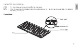
(パネルレイアウト)..............................................
(ユニットレイアウト&束線図)...................
(ブロックダイアグラム)..................................
(分解手順)...................................
(LSI 端子機能表)...................................
(IC ブロック図).........................................
(シート基板図)..............................................
(テストプログラム)...................................
(MIDI インプリメンテーションチャート)........
P-70/P-70S
ELECTRONIC PIANO
●
OPTION
(別売品)
L-70 KEYBOARD STAND
(L-70 スタンド)
L-70S KEYBOARD STAND
(L-70S スタンド)
P-70
P-70S