Yamaha NU1, Maintenance Handbook
The Yamaha NU1 is a premium hybrid piano providing the timeless touch and tone of an acoustic piano, with the added benefits of digital technology. Experience the ultimate convenience with our free downloadable reference manual, available at manualshive.com, providing you with comprehensive instructions and insights for optimal performance.
Share
Download


Reviews:
No comments
Related manuals for NU1

Nord Modular G2
Brand: Clavia Pages: 16

Telestart T91
Brand: Webasto Pages: 18

AKBWL15
Brand: Advent Pages: 12

Interactive Arranger EXR-46 OR
Brand: Roland Pages: 192

Jasmine Shisha
Brand: JWELL Pages: 14

VGK4900
Brand: Vangoa Pages: 17

KBD-USB-J Series
Brand: Stahl Pages: 16

MagicWatch MWE850
Brand: Waeco Pages: 200

Challenger Pro
Brand: Ttesports Pages: 78

MailBug
Brand: Landel Pages: 44

SK-9662
Brand: Acer Pages: 3

Accufeel G300
Brand: Acer Pages: 18

UA0B
Brand: Acer Pages: 4

SD-9080
Brand: Acer Pages: 3

Iconia W700
Brand: Acer Pages: 2286
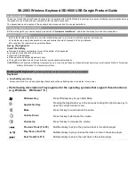
SK-2063
Brand: Acer Pages: 2

PREDATOR Aethon 300 PKB910
Brand: Acer Pages: 58

SKR-2006
Brand: Sejin Electron Pages: 9


