Yamaha Apex RX10PA, Owner'S Manual
The Yamaha Apex RX10PA Owner's Manual is an essential companion for every owner. This comprehensive manual provides detailed instructions and maintenance procedures to ensure optimal performance. Download your free copy of the manual from manualshive.com today and unleash the full potential of your Yamaha Apex RX10PA.
Share
Download


Reviews:
No comments
Related manuals for Apex RX10PA

655
Brand: J&M Pages: 26

LX200AU-2
Brand: LONCIN Pages: 65
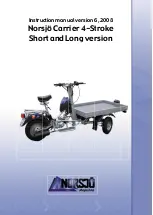
Carrier
Brand: Norsjö Pages: 32

3000-4AH
Brand: Miller Electric Pages: 20

No Limit SL50 Compact
Brand: MGI Pages: 15

DUNE 900
Brand: Troxus Pages: 12

Cuatro
Brand: Leggero Pages: 98

Minor VM Hydrostatic
Brand: Scarab Pages: 32

2010 450 SX
Brand: KTM Pages: 247

Sportsman 90
Brand: Polaris Pages: 220

VIPER 50 ST - SERVICE
Brand: E-TON Pages: 68

RECOIL iS CREW 2015
Brand: Bad Boy Pages: 60

640t
Brand: CADDY Pages: 2

XT
Brand: CaddyStar Pages: 26

Expediter EX-21 2017
Brand: Columbia Pages: 32

90 Falcon
Brand: Jula Pages: 65

Roughrider
Brand: McKee Pages: 18

VECTOR 500
Brand: Hisun Motors Pages: 67


