Yamaha 2002 FZS600, Supplementary Service Manual
The Yamaha 2002 FZS600 Supplementary Service Manual is a comprehensive user manual designed to assist owners in maintaining and repairing their motorcycle. Available for free download from manualshive.com, this manual contains detailed instructions and diagrams, ensuring smooth and hassle-free ownership. Unlock the full potential of your Yamaha FZS600 with this essential manual.
Share
Download


Reviews:
No comments
Related manuals for 2002 FZS600

FJR1300AS
Brand: Yamaha Pages: 94

FJR1300(S)
Brand: Yamaha Pages: 44

Advanced Million Color Mini Motorcycle Lighting Kit
Brand: LedGlow Pages: 3

st1300/a 2007
Brand: Honda Pages: 28

APOLLO 150
Brand: Apollo Pages: 92

ANL-H88
Brand: Akura Pages: 15

BLP0097BK
Brand: R&G Pages: 8

D3K7-4
Brand: DYNATEK Pages: 4

TS 125
Brand: MZ Pages: 82

EMPORIO ARMANI 946 2015
Brand: VESPA Pages: 416

CA-20 DS
Brand: cleanAIR Pages: 44

RST FUTURA - 2001
Brand: APRILIA Pages: 358

250 EXC-F AUS 2012
Brand: KTM Pages: 18

Classic 350
Brand: Royal Enfield Pages: 100

QuickShifter
Brand: HealTech Electronics Pages: 4

Super Extra
Brand: SAFARI Pages: 18
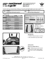
N20019
Brand: National Cycle Pages: 4

ZTechnik VStream Z2497
Brand: National Cycle Pages: 2


