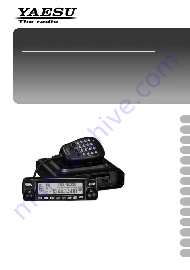
background image

C4FM/FM 

144/430 MHz

DUAL BAND TRANSCEIVER

FTM-100DR/DE

Operating Manual

Before Use

Installation and Connection

Basic Operations

Using the Memory

Scanning

Using the GPS Function

Using the APRS Function

Using the GM Function

Using the WIRES-X Function

Convenient Functions

Functions to Use as Necessary

Customizing Menu Settings and  

User Preferences

Using the Optional Accessories  

(Bluetooth Devices/Voice Unit)

Appendix

Summary of Contents for FTM-100DR/DE

Page 1: ...on Basic Operations Using the Memory Scanning Using the GPS Function Using the APRS Function Using the GM Function Using the WIRES X Function Convenient Functions Functions to Use as Necessary Customi...

Page 2: ...can Built in GPS receiver unit displays your station location and movement information Connection to external GPS devices is enabled Incorporated APRS function enables data communication of location i...

Page 3: ...n a location where it may pose a danger to the passengers where it may interfere with driving or obstruct the driver field of view Failing to take precautions accordingly may result in a vehicle accid...

Page 4: ...registered trademarks of Microsoft Corporation in the United States and other countries Bluetooth is a registered trademark of the Bluetooth SIG Other company and product names listed in this manual a...

Page 5: ...s to be pressed briefly Press for over one second Indicates that the key or switch is to be pressed for over one second The following symbols are also used in this manual Caution Explains caution to o...

Page 6: ...justing the squelch level 36 Tuning in to the frequency 37 Changing the frequency steps 37 Switching the operation mode 38 Selecting communication mode 39 Switching the modulation mode 40 Communicatin...

Page 7: ...ata 103 Functions to Use as Necessary 104 Copying the radio data to another transceiver 104 Using a micro SD memory card 104 Copying data to a micro SD memory card 104 Copying data from the micro SD m...

Page 8: ...143 Setting the APRS and data communication speed 2 DATA SPEED 145 Squelch detection and squelch jack output settings 3 DATA SQUELCH 146 Setup menu operations 10 APRS 146 Setup menu operations 11 SD 1...

Page 9: ...on the user and the surrounding people when these instructions are ignored and the product is mishandled Type and meaning of symbols Prohibited actions that must not be attempted in order to use this...

Page 10: ...may result in injury liquid leak electric shock and equipment failure When smoke or strange odors are emitted from the radio turn off the power and disconnect the power cord from the socket This may r...

Page 11: ...the device when the alarm goes off For safety reasons please pull the power plug of the DC power equipment connected to the product out of the AC socket Never touch the antenna as well This may resul...

Page 12: ...o the influence of noises from the electrical devices inverters etc fitted in the car Do not place the device on an unsteady or sloping surface or in a location where there is a lot of vibration The d...

Page 13: ...ontroller cable 3 m DC power cable with fuse attached USA EXP version DC power cable with fuse attached European version Spare fuse 15 A USA EXP version Spare fuse 15 A European version PC connection...

Page 14: ...ode status indicator Communication status Upper portion Lower portion Receiving analog audio Green Green Transmitting analog audio Red Red Receiving digital audio Green Blue Transmitting digital audio...

Page 15: ...y Briefly pressing each time switches the operating band communication mode Tip For details on the communication mode see Selecting communication mode on page 39 Pressing and holding for over one seco...

Page 16: ...le to attach the mounting bracket Firmware update switch Caution Keep the rubber cap on when not in use Main body Front MIC jack Connect the provided microphone cable CONTROL jack Connect the control...

Page 17: ...a 13 8V DC Connect the provided DC power supply cable with fuse attached EXT SP jack Connect the optional external speaker DATA jack Connect a cable for remote operation or a cable for connecting to d...

Page 18: ...to 0 Enters the numbers Switches between VFO and Memory operating mode of the operating band Activates the GM Group Monitor functions A Switches the operating band to the A band B Switches the operati...

Page 19: ...elch level while adjusting the squelch Functions as a power indicator during transmission Communication mode display Displays the current operating mode such as analog and digital using abbreviations...

Page 20: ...s to enter your call sign and memory channel tags by following the procedure below Switching the character type Press appears on the upper display Pressing each time changes the character type in the...

Page 21: ...iver Do not attempt to lift the front panel by holding onto just the knob or control cable This transceiver requires a 13 8 V DC power supply When using this transceiver in a mobile unit ensure that t...

Page 22: ...uld be installed on the dashboard or front side of the center console See Installing the front panel on page 26 Tip The GPS reception antenna is built into the front panel Where the GPS antenna is bui...

Page 23: ...50 Adjust the VSWR Voltage Standing Wave Ratio until it is 1 5 or less for an antenna with an adjusted impendence of 50 Keep the coaxial cable routing length as short as possible Installing the anten...

Page 24: ...antennas such as the Yagi antenna are suitable for communications with a specific station or a remote station in a specific direction Cautions z z Create a loop slack in the coaxial cable directly un...

Page 25: ...e 22 2 Drill four 6 mm diameter holes in the location where the bracket is to be mounted matching the positions of the bolting holes of the bracket 3 Attach the bracket Attach the bracket using the su...

Page 26: ...e front panel Attach the bracket to the front panel using the supplied screws as shown in the illustration Controller Bracket Screw 3 Adhere double sided adhesive sheet to the bracket Peel off the pro...

Page 27: ...the microphone 1 Connect the supplied microphone to the main body Plug the microphone connector into the MIC jack on the front panel until it clicks Tips When disconnecting the microphone pull the cab...

Page 28: ...bling from inside the car to the engine compartment Rout the DC power supply cable to the engine compartment passing it through a grommet 1 Feed a stiff wire from the engine compartment through the gr...

Page 29: ...e terminals and crimp or solder them to both the red and black wire ends of the DC power supply cable DC power supply cable Crimped terminal Crimping Soldering 3 Connect the red wire of the DC power s...

Page 30: ...source before connecting 1 Connect the DC power supply cable to the external power supply equipment Connect the red wire of the supplied DC power supply cable to the positive terminal of the external...

Page 31: ...heavy objects on top of it Do not touch the terminal face of the micro SD memory card with your bare hands micro SD memory cards that are initialized on other devices may not record normally on the tr...

Page 32: ...orientation Do not touch the terminal of the micro SD memory card with your hands Terminal side microSD card slot microSD memory card After turning the transceiver ON the icon appears on the top right...

Page 33: ...nts of the micro SD memory card before initialization 1 Press and hold for over one second The Setup menu appears 2 Rotate the DIAL to select 11 SD then press The menu list appears 3 Rotate the DIAL t...

Page 34: ...sign appears When turning the transceiver on thereafter the previously registered call sign will be displayed Switching the power off 1 Press and hold for over 2 seconds The screen display disappears...

Page 35: ...ion mode may be changed only for the band on the top half of the screen which is called operating band The other band displayed on the bottom half of the screen is not in operation and is called the s...

Page 36: ...may block weak signals Adjust the squelch level as required 1 Press The current squelch level is shown on the sub band display and on the SQL meter Tip In digital mode noise does not occur even if th...

Page 37: ...microphone Press UP and DWN briefly Pressing UP briefly tunes the frequency upwards Whereas pressing DWN briefly tunes the frequency in the downward direction Using the number keys Use the 0 to 9 numb...

Page 38: ...and hold for over one second The selected frequency step is set and the display returns to the previous operating display Tip To return to the previous operating display press 3 times Switching the o...

Page 39: ...ignal received icon differs depending on the received signal The AMS function operation can be changed from the Setup menu setting See Setting the transmission mode when using the AMS function 3 AMS T...

Page 40: ...Rotate the DIAL to select 2 TX RX then press The menu list appears 4 Rotate the DIAL to select 1 ANALOG MODE SELECT then press The modulation mode setting value appears 5 Rotate the DIAL to select the...

Page 41: ...ue 2 Speak into MIC on the microphone Tip Keep the microphone about 5 cm away from your mouth LOCK P3 P2 P1 7 1 4 8 2 0 5 9 B A C D 3 6 P4 LAM P DTMF MICROPHONE MH 48 ABC JKL TUV GHI PQRS DEF MIC MNO...

Page 42: ...of the microphone can be adjusted 1 Press and hold for over one second The Setup menu appears 2 Rotate the DIAL to select 2 TX RX then press The menu list appears 3 Rotate the DIAL to select 2 MIC GA...

Page 43: ...having an 100 0 Hz tone signal are emitted on the frequency lower than reception frequency by 5 MHz Depends on the transceiver version Tip From the Setup menu you can change the repeater setting 8 CO...

Page 44: ...L FREQ and then press the CTCSS tone frequency will be displayed 5 Turn the DIAL to change and select the different tone frequency 6 Press for more than one second to set the new tone and return to th...

Page 45: ...G then press The menu list appears 3 Rotate the DIAL to select 8 BEEP then press The volume setting value appears 4 Rotate the DIAL to select the desired volume level 1 OFF 2 LOW 3 HIGH Tip The defaul...

Page 46: ...nlock the DIAL and keys UNLOCK will be displayed on the screen Adjusting the date and time The FTM 100DR DE transceiver has a built in clock Set the time and date before using the radio Also the clock...

Page 47: ...Minute display blinks Tip Press to go back appears on the upper side 13 Rotate the DIAL to select the minute 14 Press The date and time are set and the screen returns to the setting screen 15 Press an...

Page 48: ...LCD BRIGHTNESS then press The brightness level adjustment screen appears 4 Rotate the DIAL to select the desired brightness level The brightness level can be selected from the following 7 levels MIN 2...

Page 49: ...ansceiver settings and memory content may be restored to the defaults 1 Press and hold for over one second The Setup menu appears 2 Rotate the DIAL to select 13 RST CLONE then press The menu list appe...

Page 50: ...unction clears all information registered to the memory channels Be sure to write memory data down on paper or back up the data on a micro SD memory card For instructions on saving the data onto a bac...

Page 51: ...annel and PMS memory channel Operating frequency Modulation mode Memory tag Repeater information Tone information DCS information Memory skip information Transmit power Digital mode and analog mode in...

Page 52: ...Press Completes memory registration and displays the frequency and the memory channel number on the screen Tips The frequency which has been registered to a memory channel can be overwritten with a n...

Page 53: ...creen Tip Change the frequency by rotating the DIAL to return to VFO mode LOC K P3 P2 P1 7 1 4 8 2 0 5 9 B A C D 3 6 P4 LA MP DTMF MICROPHONE MH 48 ABC JKL TUV GHI PQRS DEF MNO WXYZ MIC Press P2 again...

Page 54: ...to tune to the desired home channel frequency 3 Press and hold for over one second The MEMORY WRITE screen appears 4 Rotate the DIAL to select HOME 5 Press The overwrite confirmation screen appears 6...

Page 55: ...channel from which memories are to be cleared 4 Press appears on the upper side The erase confirmation screen appears 5 Rotate the DIAL to select OK then press Erases the memory and clears the displa...

Page 56: ...e following characters can be entered as a memory tag Alphabet capital small letters numbers symbols Example Assigning a name like YM Grp01 1 Press and hold for over one second The MEMORY WRITE screen...

Page 57: ...ress appears on the upper side A space is entered and the cursor moves to the right 9 Press appears on the upper side Upper case letters can be entered 10 Rotate the DIAL to select G then press appear...

Page 58: ...menu appears 2 Rotate the DIAL to select 3 MEMORY then press The menu list appears 3 Rotate the DIAL to select 1 ALPHA TAG SIZE then press The setting options appear 4 Rotate the DIAL to select the d...

Page 59: ...he next blank memory channel 3 Rotate the DIAL if necessary to select the memory channel to which the transmit frequency is to be registered Tip Pressing briefly skips memory channels in steps of 100...

Page 60: ...ress 3 Rotate the DIAL to select 10 MIC PROGRAM KEY then press The microphone program key setting screen appears 4 Rotate the DIAL to select the program key P1 to P4 where the WX function is going to...

Page 61: ...ces such as storms and hurricanes the NOAA National Oceanic and Atmospheric Administration sends a weather alert accompanied by a 1050 Hz tone and subsequent weather report on one of the NOAA weather...

Page 62: ...frequency direction During scanning the decimal point of the frequency display blinks Once the transceiver receives a signal the transceiver continuously receives it until the signal disappears and r...

Page 63: ...estart scanning 2 seconds after the signal disappears BUSY 3 Stop scanning and receive that frequency HOLD 1 Press and hold for over one second The Setup menu appears 2 Rotate the DIAL to select 5 SCA...

Page 64: ...ears Tips The scanning direction UP DOWN can be set from 5 SCAN 2 SCAN DIRECTION in the Setup menu This direction setting is also applied to scanning performed using one of the P1 to P4 keys on the mi...

Page 65: ...t 3 MEMORY and then press The menu list appears 3 Rotate the DIAL to select 2 MEMORY SCAN TYPE then press The setting options appear 4 Rotate the DIAL to select the desired option 1 ALL MEMORY Scans a...

Page 66: ...IAL to select the desired memory channel 4 Press twice appears on the upper side On the right side of the memory channel number display lights up This indicates the SELECT state The memory channels ma...

Page 67: ...he previously viewed screen 7 Press and hold UP or DWN on the microphone for over one second Scanning of the specified memory channels begins Tips Pressing UP scans in the memory channel numbers in th...

Page 68: ...tered to the PMS memory channels Register the lower limit of the desired scanning frequency range to the memory channel LP and the upper limit to the memory channel UP One pair of PMS memories with th...

Page 69: ...ond Programmable memory scanning will begin Tips To cancel programmable memory scanning press PTT on the microphone this does not cancel PMS mode To cancel PMS mode when programmable memory scanning s...

Page 70: ...sappears the dual reception starts again Caution When shipped from the factory the 144 MHz band home channel is set to 145 000 MHz while the 430 MHz band home channel is set to 433 000 MHz The registe...

Page 71: ...ng 1 AUTO 5 Press and hold for over one second Sets the dual reception restart setting and returns the display to the previously viewed screen Setting the channel signal reception time when using the...

Page 72: ...t of Defense as a military system It receives signals from 3 or more of about 30 GPS satellites flying at an altitude of about 20 000 km and displays the current position latitude longitude altitude w...

Page 73: ...rground When used behind a solar energy reflecting glass Areas with strong magnetic fields When the GPS is not in use for an extended period of time Locating satellites may take several minutes when u...

Page 74: ...municating 1 Press once briefly Displays the current location information of the received station on the left side of the frequency display The screen displays the compass indicating the direction to...

Page 75: ...ame GPSyymmdd log The portion yymmdd indicates the saving start time in yy year mm month and dd day Checking the route using a personal computer The route can also be displayed on a computer with comm...

Page 76: ...andard used all around the world 2 TOKYO MEAN Use the Japanese geodetic reference system for positioning Reduces the chance of inaccuracies while positioning in Japan Tokyo Tips When the geodetic refe...

Page 77: ...the format developed by Bob Bruninga of WB4APR Upon receiving an APRS signal from another station information such as the direction and distance to that station from your station the speed of the sta...

Page 78: ...the GM function may also be used to exchange data such as messages and images between group members Tips The GM function does not work while in the analog mode When the GM function is activated the op...

Page 79: ...designated frequency on the operating band 2 Press The GM function activates and displays up to 24 stations transmitting in the GM mode on the same frequency or stations running in DN mode within the...

Page 80: ...to communicate with other users world wide regardless of the distance When the transceiver is connected to WIRES X the call sings of other stations and rooms on the WIRES X are displayed To establish...

Page 81: ...transmit a signal using a CTCSS code use the key to switch the communication mode to AMS Auto Mode Select function or analog FM mode Selecting the tone frequency The tone frequency can be selected fro...

Page 82: ...lowing order OFF TONE ENC TONE SQL REV TONE DCS PR FREQ PAGER DCS ENC TONE DCS DCS TSQL To display these squelch types from the Setup menu select 4 SIGNALING 9 SQL EXPANSION followed by 1 ON Instead o...

Page 83: ...ne second Tips Rotating the DIAL changes the squelch type in the following order OFF TONE ENC TONE SQL REV TONE DCS PR FREQ PAGER DCS ENC TONE DCS DCS TSQL The squelch types may also be selected from...

Page 84: ...DCS code use the key to switch the communication mode to AMS Auto Mode Select function or analog mode FM Selecting the DCS code The DCS code can be selected from 104 digital codes between 023 and 754...

Page 85: ...OFF TONE ENC TONE SQL REV TONE DCS PR FREQ PAGER DCS ENC TONE DCS DCS TSQL To display these squelch types from the Setup menu select 4 SIGNALING 9 SQL EXPANSION followed by 1 ON Instead of following t...

Page 86: ...code 1 Press and hold for over one second The Setup menu appears 2 Rotate the DIAL to select 4 SIGNALING then press The menu list appears 3 Rotate the DIAL to select 6 PAGER CODE then press The pager...

Page 87: ...Press and hold for over one second The Setup menu appears 2 Rotate the DIAL to select 4 SIGNALING then press The menu list appears 3 Rotate the DIAL to select 4 SQL TYPE then press 4 Rotate the DIAL t...

Page 88: ...code then press Select the first part of the code from 01 to 50 Tip The default setting 05 6 Rotate the DIAL to select TX CODE 2 then press The code blinks 7 Rotate the DIAL to select the code then p...

Page 89: ...or over one second The Setup menu appears 2 Rotate the DIAL to select 4 SIGNALING then press The menu list appears 3 Rotate the DIAL to select 8 BELL RINGER then press 4 Rotate the DIAL to select the...

Page 90: ...m the Setup menu select 4 SIGNALING 4 SQL TYPE followed by DCS ENC The DCS code is sent during transmission To use this function from the Setup menu select 4 SIGNALING 9 SQL EXPANSION followed by 1 ON...

Page 91: ...ering the DTMF code 1 Press and hold for over one second The Setup menu appears 2 Rotate the DIAL to select 4 SIGNALING then press The menu list appears 3 Rotate the DIAL to select 5 DTMF MEMORY then...

Page 92: ...OFF 5 Press and hold for over one second Returns the display to the previously viewed screen and displays on the top right side of the screen Tip You can also return to the previous screen by pressing...

Page 93: ...the display to the previously viewed screen and displays on the top right side of the screen Tip You can also return to the previous screen by pressing 3 times 6 While pressing and holding PTT press...

Page 94: ...pears 2 Rotate the DIAL to select 8 CONFIG then press The menu list appears 3 Rotate the DIAL to select 13 APO then press Displays the screen where the remaining time until the power turns off is set...

Page 95: ...r one second The Setup menu appears 2 Rotate the DIAL to select 8 CONFIG then press The menu list appears 3 Rotate the DIAL to select 14 TOT then press The screen is displayed where the time remaining...

Page 96: ...of digital mode as follows For details see Selecting communication mode on page 39 V D mode simultaneous voice data communication mode Voice FR mode voice full rate mode Data FR mode high speed data c...

Page 97: ...appears on the upper side to jump to the bottom of the list When there are many files it may take a while to jump to the bottom of the list Press PTT to cancel the operation halfway Press appears on t...

Page 98: ...cel then press Downloading messages or images When there is a message or image sent in digital mode from a station on the same operating frequency the content of the message or image is displayed for...

Page 99: ...essage or image data Creating and sending a new message Create a new message and send 1 Press and hold for over one second Displays LOG SELECT screen 2 Rotate the DIAL to select GM MESSAGE then press...

Page 100: ...T Send pictures QRX on my way QRZ wait for you QSY Pick me up Good morning Thank you Good job OK Good day urgent Good evening 1 Follow the steps 1 through 3 of Creating and sending a new message on pa...

Page 101: ...ing and sending a new message on page 99 to input a text message Tip Alphanumeric characters including symbols can be used 2 Press 3 Press appears on the upper side Displays the routine message field...

Page 102: ...Press appears on the upper side Displays the message entry screen 5 Enter the reply message See Creating and sending a new message on page 99 to enter the reply message Tips When replying the call si...

Page 103: ...en GM MESSAGE is selected the GM MESSAGE screen appears When GM PICT is selected the GM PICT screen appears 3 Rotate the DIAL to select the data you want to forward then press Displays the selected da...

Page 104: ...g data to a micro SD memory card 1 Insert a micro SD memory card into the transceiver Tip See Inserting a micro SD memory card on page 32 2 Press and hold for over one second The Setup menu appears 3...

Page 105: ...pied 3 Press and hold for over one second The Setup menu appears 4 Rotate the DIAL to select 11 SD then press The menu list appears 5 Rotate the DIAL to select 1 BACKUP then press Displays the screen...

Page 106: ...nal clone cable CT 166 to the DATA jack on the rear side of the transceivers 3 Turn on both transceivers 4 Press and hold for over one second The Setup menu appears 5 Rotate the DIAL to select 13 RST...

Page 107: ...ns to the previously viewed operating screen 12 Turn off the both transceivers then disconnect the clone cable Cautions z z When ERROR appears on the screen during the copy clone operation the copy cl...

Page 108: ...f the DATA jack is shown below DATA jack PKD packet data input GND PSK PTT RX 9600 9 600 bps packet data output RX 1200 1 200 bps packet data output PK SQL squelch control TXD serial data output trans...

Page 109: ...iver PC GND CTS data communication control RTS data communication control Tips Make sure to turn off the transceiver before connecting any cables When using the SCU 20 PC connection cable install the...

Page 110: ...e following order 4800 bps 9600 bps 19200 bps 38400 bps 57600 bps Tip The default setting 9600bps 9 Press and hold for over one second Returns the display to the previously viewed screen Transmits the...

Page 111: ...ut transceiver PC RXD serial data input transceiver PC CTS data communication control RTS data communication control brown PKD packet data input thick black GND red PSK PTT orange RX 9600 9 600 bps pa...

Page 112: ...ontrol RTS data communication control DIN 6 pin PKD packet data input GND PSK PTT RX 9600 9 600 bps packet data output RX 1200 1 200 bps packet data output PK SQL squelch control Tips Make sure to tur...

Page 113: ...PEED then press 8 Rotate the DIAL to select the desired communication speed then press The setting changes in the following order 4800 bps 9600 bps 19200 bps 38400 bps 57600 bps Tip The default settin...

Page 114: ...level to the TNC from the transceiver 19 Adjust the TNC output level Sets the input level to the transceiver Caution Transmitting a large amount of data may take a long time causing for the transceive...

Page 115: ...aker is connected to the EXT SP jack the internal speaker does not output audio Caution When connecting an external speaker other than the optional MLS 200 M10 to the EXT SP jack on the rear of the tr...

Page 116: ...tem then select The menu list appears 3 Rotate the DIAL to select the item to be set then press 4 Rotate the DIAL to change the setting value 5 Press and hold for over one second or press PTT The sele...

Page 117: ...2 sec 4 sec 6 sec 8 sec 10 sec 20 sec 30 sec 60 sec CONTINUE 7 LOCATION SERVICE Sets your location information display in digital mode ON OFF For details refer to the GM Function Instruction Manual 8...

Page 118: ...vates the alert sound when detecting stations within communication range OFF ON 2 MESSAGE POPUP Activates deactivates the pop up message display OFF ON 3 RADIO ID Displays the transceiver IDs uneditab...

Page 119: ...NORMAL WIDE 12 UNIT Sets the unit used for the display METRIC INCH Depends on the transceiver version 13 APO Sets the APO action time OFF 0 5 hour to 12 0 hour 14 TOT Sets the time out timer OFF 1 min...

Page 120: ...APRS POP UP Sets the duration time for displaying the pop up beacons and messages BEACON OFF 3 sec 5 sec 10 sec HOLD MESSAGE OFF 3 sec 5 sec 10 sec HOLD MYPACKET OFF ON 8 APRS RINGER Sets the audio a...

Page 121: ...ESU GROUP 5 GROUP 6 BULLETIN 1 BLN BULLETIN 2 BLN BULLETIN 3 BLN 18 MESSAGE REPLY Sets the automatic response for received messages REPLY OFF ON CALLSIGN REPLY TEXT 19 MY POSITION SET Sets your locati...

Page 122: ...VE PTT MODE MOMENTARY TOGGLE VOX ON OFF GAIN HIGH LOW 2 VOICE MEMORY Sets the voice memory function PLAY REC FREE 5min LAST 30sec ANNOUNCE AUTO MANUAL LANGUAGE JAPANESE ENGLISH VOLUME HIGH MID LOW 13...

Page 123: ...t the information to display on the sub display 1 SUB BAND Displays the sub band operating information 2 TIME Displays the time 3 VDD Displays the voltage Tip The default setting 1 SUB BAND 5 Press an...

Page 124: ...The Setup menu appears 2 Rotate the DIAL to select 1 DISPLAY then press 3 Rotate the DIAL to select 4 GPS INFORMATION then press 4 Rotate the DIAL to select the GPS information to be displayed 1 LOCAT...

Page 125: ...GAIN You can set the microphone sensitivity microphone gain For details see Adjusting the microphone sensitivity on page 42 Setting the transmission mode when using the AMS function 3 AMS TX MODE You...

Page 126: ...d signal Always switches to DN mode for transmission 5 TX VW FIXED Automatically selects one of the 4 communication modes according to the received signal Always switches to VW mode for transmission T...

Page 127: ...d Tip The default setting 1 OFF 5 Press and hold for over one second Sets the squelch type and returns the display to the previously viewed screen Setting the digital mode squelch code 5 DIGITAL SQL C...

Page 128: ...to select 2 TX RX then press 3 Rotate the DIAL to select 6 DIGITAL POPUP TIME then press 4 Rotate the DIAL to select the time to display the pop up window 1 OFF 2 2 sec 3 4 sec 4 6 sec 5 8 sec 6 10 s...

Page 129: ...Press and hold for over one second The Setup menu appears 2 Rotate the DIAL to select 2 TX RX then press 3 Rotate the DIAL to select 8 STANDBY BEEP then press 4 Rotate the DIAL to switch the setting...

Page 130: ...N Reduces the FM modulation to half 2 OFF Uses the normal FM modulation Tip The default setting 2 OFF 5 Press and hold for over one second Returns the display to the previously viewed screen Setup men...

Page 131: ...type 4 SQL TYPE Select the squelch type For details see Communicating with specific stations on page 81 Registering the DTMF code 5 DTMF MEMORY The maximum of 16 digit DTMF codes can be registered fo...

Page 132: ...ame squelch for transmission and reception Tip The default setting 2 OFF 5 Press and hold for over one second Sets the squelch type for transmission and reception and returns the display to the previo...

Page 133: ...rection or lower direction of the frequencies or memory channels when scanning on that key For details on how to assign the function to P1 to P4 see Setting the program keys on the microphone 10 MIC P...

Page 134: ...nnel when using the dual reception function For details see Setting the channel signal reception time when using the dual reception function on page 71 Setup menu operations 6 GM The GM group monitor...

Page 135: ...the internal clock time display 24 hour display or 12 hour display 1 Press and hold for over one second The Setup menu appears 2 Rotate the DIAL to select 8 CONFIG then press 3 Rotate the DIAL to sel...

Page 136: ...time zone and returns the display to the previously viewed screen Using the auto repeater shift function 4 AUTO REPEATER SHIFT When communicating using a repeater channel the repeater offset frequency...

Page 137: ...setting Differs depending on frequency 5 Press and hold for over one second Sets the repeater shift direction and returns the display to the previously viewed screen Setting the repeater shift width 6...

Page 138: ...receiver frequency Select A for the normal operation 1 Press and hold for over one second The Setup menu appears 2 Rotate the DIAL to select 8 CONFIG then press 3 Rotate the DIAL to select 9 CLOCK TY...

Page 139: ...S HOME Recalls the home channel DCS CODE Selects the DCS code TONE FREQ Selects the tone frequency RPT SHIFT Activates the repeater shift function REVERSE Reverse function TX POWER Sets the transmissi...

Page 140: ...eceives the aircraft band and information band as well Tip The default setting 1 NORMAL 5 Press and hold for over one second Sets the reception range and returns the display to the previously viewed s...

Page 141: ...en a Bluetooth unit is installed in the transceiver it may identify and be paired with the Bluetooth headset in use See Identifying the Bluetooth headset on page 155 Setting the geodetic reference sys...

Page 142: ...c reference system and returns the display to the previously viewed screen Tip Select 1 WGS 84 for the normal operation Setting the interval for saving the GPS location information 17 GPS LOG Set the...

Page 143: ...the DIAL to select the desired communication speed then press The setting switches as follows 4800 bps 9600 bps 19200 bps 38400 bps 57600 bps Tip The default setting 9600 bps 6 Rotate the DIAL to sele...

Page 144: ...put as JQ1YBG 14 NMEA 8 Displays the last 8 digits of the call sign Example JQ1YBG 14 is shortened to Q1YBG 14 NMEA 7 Displays the last 7 digits of the call sign Example JQ1YBG 14 is shortened to 1YBG...

Page 145: ...tup menu Tip The default setting ALL 14 Press and hold for over one second Sets the COM port and returns the display to the previous operating screen Setting the APRS and data communication speed 2 DA...

Page 146: ...unction which enables receiving and transmitting GPS location data information and messages in the APRS format For details refer to the APRS Instruction Manual download from Yaesu website Setup menu o...

Page 147: ...rophone For details see Using the voice memory on page 160 Setup menu operations 13 RST CLONE Resetting the transceiver settings 1 FACTORY RESET You can restore the transceiver configuration and memor...

Page 148: ...eset setting and returns the display to the previously viewed screen To cancel the Setup menu without any change select Cancel then press 5 Press and hold for over one second Returns the display to th...

Page 149: ...channels in ascending order of frequency The transceiver restarts Resetting the APRS setting 6 APRS RESET Reset the APRS setting 1 Press and hold for over one second The Setup menu appears 2 Rotate t...

Page 150: ...on the upper row The cursor movers to the right Tips Up to 10 alphanumeric characters including hyphen and slash may be input To switch the input screen uppercase letters lowercase letters symbols and...

Page 151: ...ver not all the functions are guaranteed to work properly Mounting the Bluetooth unit BU 2 What to prepare Bluetooth unit BU 2 optional Phillips head screwdriver Mounting procedure Cautions z z Avoid...

Page 152: ...et on the main board to completely remove the top cover from the transceiver Caution When unplugging the speaker cable do not pull the cable Be sure to hold the connector part 7 Remove the 2 screws fr...

Page 153: ...ly switching to transmit when you begin speaking VOX The VOX gain may be set to automatically switch to transmit upon detecting voices including low volume sounds 1 Turn on the transceiver 2 Press and...

Page 154: ...12 Rotate the DIAL to select MOMENTARY or TOGGLE MOMENTARY Remains in transmit mode while pressing and holding PTT on the headset TOGGLE Pressing PTT on the headset each time switches between transmi...

Page 155: ...ed This process is called pairing The PIN codes are used for registering each other Through pairing interference and improper interception can be prevented When using the Bluetooth headset together wi...

Page 156: ...ernately between red and blue 6 Press Pairing appears When paring successfully completes Completed appears and the display returns to the menu list screen The indicator on BH 2A blinks blue Caution If...

Page 157: ...de the sphere of communication 1 When not using the VOX function 1 Turn on the headset The receive audio will be heard from the headset speaker 2 Briefly press PTT on the headset The transceiver goes...

Page 158: ...edure Cautions z z Avoid touching the IC components with your hands as the semiconductors may be damaged by static electricity z z Note that installation of optional items may incur additional labor c...

Page 159: ...unplugging the speaker cable do not pull the cable Be sure to hold the connector part 7 Refer to the illustration on the right and carefully plug the FVS 2 into the connector Caution Check the direct...

Page 160: ...e memory operation 1 Turn on the transceiver 2 Press and hold for over one second The Setup menu appears 3 Rotate the DIAL to select 12 OPTION then press 4 Rotate the DIAL to select 2 VOICE MEMORY the...

Page 161: ...in the bottom area of the screen 2 Press appears on the display Recording begins Tip The recording time you set from 12 OPTION 2 VOICE MEMORY in the Setup menu appears below REC 3 Press appears on th...

Page 162: ...k number ALL 1 2 If ALL is selected all of the recorded tracks will be played back in order 3 Press and hold for over one second appears on the display Playback begins After playing to the end of the...

Page 163: ...zed Setting how an announcement is initiated Selecting the language Setting the announcement volume level Muting the receive audio while announcements are being made 1 Press and hold for over one seco...

Page 164: ...DIAL each time switches the setting between on and off ON Mutes the reception sound when speaking or playing recorded voice OFF Does not mute the reception sound even when speaking or playing recorded...

Page 165: ...ne MH 42C6J Multifunctional DTMF microphone MH 48A6JA Same as the one provided Waterproof Bluetooth headset monaural BH 2A Charging cradle for BH 2A CD 40 Battery charger for CD 40 PA 46A z z Desktop...

Page 166: ...e of the DC power supply cable blows and the transceiver becomes inoperable correct the cause of the problem and then replace the fuse with a new one of the correct 15 Amp rating Caution When replacin...

Page 167: ...equency or DCS code corresponding to the set code are received z z Is the external speaker connected Properly connect a speaker with an impedance of 4 to 16 z z Is the Bluetooth headset in use Disable...

Page 168: ...refer to the calculation formulas below n is any integer Depending on the combination of the frequencies received simultaneously there may also be fluctuations in the receiver sensitivity z z Recepti...

Page 169: ...ge Norminal 13 8 V DC negative ground Operating 11 7 15 8 V DC negative ground Current consumption 0 5 A receive 11 A 50 W TX 144 MHz 12 A 50 W TX 430 MHz Operating temperature 4 F to 140 F 20 C to 60...

Page 170: ...M 0 25 V for 12 dB SINAD 420 470 MHz FM 0 2 V typ for 12 dB SINAD 470 520 MHz FM 0 2 V for 12 dB SINAD 800 900 MHz FM 0 4 V typ for 12 dB SINAD 900 999 99 MHz FM 0 8 V typ for 12 dB SINAD Cellular blo...

Page 171: ...7 Connecting the front panel to the main body 27 Connecting the microphone 27 Connecting the power supply 28 Connecting the transceiver 27 Connecting to a computer 108 Copying data from the micro SD m...

Page 172: ...ing routine messages 101 Registering the DTMF code 91 131 Registering to the memory channel 51 Registering to the programmable memory channels 68 Removing the micro SD memory card 32 Replacing the fus...

Page 173: ...ion USA Version Only 132 Setting up the micro SD memory card 31 Setting up the screen display 123 Setting your location information display 128 Setup menu basic operations 116 Setup menu listing 117 S...

Page 174: ...nce and 2 this device must accept any interference including interference that may cause undesired operation of the device Le pr sent appareil est conforme aux CNR d Industrie Canada applicables aux a...

Page 175: ...rms to the essential requirements of directive as included in following standards Health 1999 5 EC Art 3 1 a EN 62311 2008 Safety 1999 5 EC Art 3 1 a EN 60950 1 2006 A2 2013 EMC 1999 5 EC Art 3 1 b EN...

Page 176: ...U USA 6125 Phyllis Drive Cypress CA 90630 U S A YAESU UK Unit 12 Sun Valley Business Park Winnall Close Winchester Hampshire SO23 0LB U K Copyright 2015 YAESU MUSEN CO LTD All rights reserved No porti...

Reviews: