Xycom 1341, User Manual
The Xycom 1341 User Manual is essential for mastering the features and functions of this innovative product. Download the manual for free at manualshive.com to access step-by-step instructions, troubleshooting tips, and helpful resources. Ensure optimal performance and maximize the benefits of your Xycom 1341 with this comprehensive manual.
Share
Download


Reviews:
No comments
Related manuals for 1341

PS01a
Brand: SEH Pages: 20

57-1543
Brand: K&N Pages: 2

Epicure PN AFE36H3 Series
Brand: Dacor Pages: 8
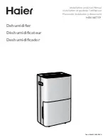
HEN70ETFP
Brand: Haier Pages: 36

CXW-219-D69
Brand: Haier Pages: 13
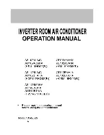
H2SM-21HX03
Brand: Haier Pages: 27

HRFZ-250D AA
Brand: Haier Pages: 104

31-5120
Brand: Westin Pages: 5

123 SCHLEIFENPROFI VX
Brand: HRMTEC Pages: 22

Toftejorg SaniMidget SB Series
Brand: Alfa Laval Pages: 28

1037290
Brand: First Alert Pages: 16

PROCRISTAL UV-C 11W
Brand: JBL Pages: 116

Amulet M Phantom
Brand: Trance Audio Pages: 2

RFL 9300
Brand: RFL Electronics Pages: 553

50MF231D - Hook Up Guide
Brand: Magnavox Pages: 102

om-3
Brand: Olympus Pages: 52
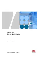
VR2
Brand: Huawei Pages: 12

21-699
Brand: AEM Pages: 14


