background image


XL-PBW224CW 


Coaxial Integrated Access System 


V1.0


Summary of Contents for XL-PBW224CW

Page 1: ...XL PBW224CW Coaxial Integrated Access System V1 0 ...

Page 2: ...may result in the power cord is damaged resulting in fire or electric shock 2 In the use of the former make sure that the environment of temperature and humidity in accordance with the products required Since the air conditioned room to move this product to the natural temperature may cause the product surface or internal components have condensed water vapor please be the product of natural dry b...

Page 3: ...istics 9 3 2 3 IP Address distribution 9 3 3PLC Page 10 3 3 1 PLC The basic configuration system information 10 3 3 2 PLC System Equipment style 11 3 3 3 PLC Flow Control Systems and Equipment 11 3 3 4 PLC Systems to send and receive data packets statistics 12 3 4 Ethernet Page 13 3 4 1 Ethernet link layer information 13 3 4 2 Ethernet Systems to send and receive data packets statistics 13 3 4 3 E...

Page 4: ...4 1 2 Environmental Characteristics 18 4 1 3 Application Characteristics 18 4 1 4 Manage and Maintain 19 4 1 5 Adjust Technology 19 4 1 6 Instruction and ports 19 4 2 Frequently Questions answer ...

Page 5: ...without prejudice to the normal work of the existing CATV system not to the existing network of large scale changes the Data CATV signal and the signal with the original transmission for carrying IP based data voice and video and other multimedia services The transfor mation of the less cost and engineering will be the original one wa y CATV network into a two way digital and can carry multimedia ...

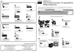
Page 6: ...2 1 1 1 XL PBW224CW End Products Appearance ...

Page 7: ...Ethernet LAN network Interface Indicator LAN port connected to the network Flicker There are data transmission 1 1 3 Ports Item Meaning Description POWER Power port Input 100V 265V Ethernet Network Port 10 100M Adaptive connected computer RF IN TV Signal port Connect TV Signal RF DATA OUT Synthesis of signal output Connect terminal equipment XL PB224C terminal equipment connected diagram as shown ...

Page 8: ...e voltage and current at the same time is also in line with XL PBW224CW work 2 The exchange received a power outlet plugs XL PBW224CW to boot 3 Boot after the POWER indicator light about 10 seconds after the System indicator will begin to flicker the system began to self test and then after about 10 seconds such as monitoring systems are completed and normal System indicator will Always 4 At this ...

Page 9: ...condition monitoring of private IP addresses you can use a web browser through the IP address of the page to enter the state of the state of observation equipment 3 1 Login Page In this case to use the IE browser IP address 192 168 2 1 as an example enter in the address bar 192 168 2 1 landing interface appears enter your user name admin and password admin as shown in Figure 3 1 Pic 3 1 ...

Page 10: ...6 3 2 Bridge Page Pic 3 2 1 3 2 1 The basic configuration system information Pic3 2 2 ...

Page 11: ...3 2 2 BridgeSystems to send and receive data packets statistics 7 Pic3 2 3 3 2 3 IP Address distribution Pic3 2 4 ...

Page 12: ...3 3 PLC Page 8 Pic3 3 1 3 3 1 PLC System Equipment Information Pic3 3 2 ...

Page 13: ... 2 PLC System Equipment style 13 Pic3 3 3 3 3 3 PLC Flow Control Systems and Equipment Click on TC ACTIVE In the Rate column need to limit the rate of input Click Save Configuration button to save Pic3 3 4 ...

Page 14: ...3 3 4 PLC Systems to send and receive data packets statistics 14 Pic 3 Pic 5 3 4 Ethernet Page Pic 3 Pic 1 ...

Page 15: ...3 4 1 Ethernet link layer information 15 Pic 3 Pic 2 3 4 2 Ethernet Systems to send and receive data packets statistics Pic 3 Pic 3 ...

Page 16: ...3 5 1 Current software version information 16 Click on TC ACTIVE In the Rate column need to limit the rate of input Click Save Configuration button to save Pic 3 Pic 4 3 5 Software Page ...

Page 17: ...3 5 1 Current software version information 17 Pic 3 Pic 2 3 5 2 Delete procecures Backup software to choose a name Click Remove button Pic 3 Pic 3 ...

Page 18: ...r promotion procedures need to upload the file name Enter FTP server IP address Enter the display name in the machine Click send button 图 3 Pic 4 3 5 4 Change Keywords Enter the need to amend the new password Re enter new password to confirm ...

Page 19: ...19 Pic 3 Pic 5 3 6 VLAN Page Enter the need for the VID click add button to add a VLAN Pic 3 Pic ...

Page 20: ...896 Carrier Communication frequency division duplex full time Security 45dBuV Network tolerance of the attenuation 70dB 0 60dB range of the average throughput of 50Mbps 70dB at 35Mbps Output 110 135dBuV Transmission media and impedance TV Cable 75Ω Power supply AC 100V 265V 4 1 2 Environmental Characteristics Temperature 10 55 C Working humidity 10 90 4 1 3 Application Characteristics Security VLA...

Page 21: ...21 IP Multicast IGMP snooping through the realization of 802 3 multicast and m ...

Page 22: ...ation TDMA CSMA CA Modulation Way None BPSK QPSK 16QAM 64QAM 256QAM 1024QAM 4 1 6 Instruction and Ports LED Power indicator Power power equipment status indicator Ethernet Ethernet indicator light System System Indicator Data Data Link light Interface type RJ45 output data interface 1 or 2 F type coaxial mixed data entry interface RF TV Signal output interface DC Power Interface ...

Page 23: ...e another card slot if the replacement card is not enough please No TV signal output 1 Make sure Cable interface has been properly connected 2 Make sure that the normal instructions System indicator 3 Make sure that operators have to apply for opening of related businesses Can not access the Internet Take model commonly used as an example already installed on your computer dial up software explain...

Reviews: