Westermo 3623-071001, User Manual
Looking for the User Manual for the Westermo 3623-071001? Look no further! Download the complete manual for free from our manualshive.com, providing you with detailed instructions, troubleshooting tips, and all the information you need to maximize the benefits of this incredible product.
Share
Download


Reviews:
No comments
Related manuals for 3623-071001

Rangebooster N 650 Access Point DAP-1353
Brand: D-Link Pages: 67

DWL-1000AP
Brand: D-Link Pages: 8
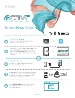
COVR-2202
Brand: D-Link Pages: 2

DAP-1155
Brand: D-Link Pages: 3

Air Premier DAP-2695
Brand: D-Link Pages: 39
AirPlus DI-714P+
Brand: D-Link Pages: 5
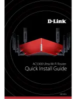
AC5300
Brand: D-Link Pages: 12
SharePort DIR-825
Brand: D-Link Pages: 20
Express EtherNetwork DI-604
Brand: D-Link Pages: 49

UniFi Switch Flex
Brand: Ubiquiti Pages: 10

WNRT-625
Brand: Planet Pages: 42

FLEX4G-LITE
Brand: BridgeWave Pages: 84

Connect-4GE
Brand: Teldat Pages: 24

Skyr@cer WBR 354G
Brand: Topcom Pages: 104

LAPN300
Brand: Linksys Pages: 112

WAP51AB - Instant Wireless - Access Point
Brand: Linksys Pages: 2

Integra-W Series
Brand: SAF tehnika Pages: 82

Videomesh 2200 Series
Brand: Fluidmesh Pages: 30


