Xinje DP-7022P, Abridged User Manual
The Xinje DP-7022P Abridged User Manual is an essential tool for operating and getting the most out of your device. It provides concise yet comprehensive instructions for quick and efficient usage. Download this manual for free from our website manualshive.com to unlock the full potential of your Xinje DP-7022P.
Share
Download


Reviews:
No comments
Related manuals for DP-7022P

DP 196
Brand: Paoli Avvitatori Pages: 52

PHSSA 12-Li A1
Brand: Parkside Pages: 112

SWITCH HHS1200
Brand: Hammerhead Pages: 36

DP 1000
Brand: Paoli Avvitatori Pages: 52

DP 176
Brand: Paoli Avvitatori Pages: 52

DTD155Z
Brand: Makita Pages: 68
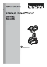
TW004GM201
Brand: Makita Pages: 16
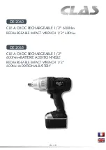
OE 2060
Brand: CLAS Pages: 20

2934 Series
Brand: Ingersoll-Rand Pages: 8

215G
Brand: Ingersoll-Rand Pages: 12

DTD153Z
Brand: Makita Pages: 60

R86012
Brand: RIDGID Pages: 24

WX291
Brand: Worx Pages: 104

UP898-6B
Brand: Urrea Pages: 8

UP772HA
Brand: Urrea Pages: 8

WT03056
Brand: TOOL WAREHOUSE Pages: 15

620409
Brand: Ribimex Pages: 57

8791810
Brand: EXTOL Pages: 32


