background image

UK/IE

INSTALLATION, COMMISSIONING AND SERVICING INSTRUCTIONS

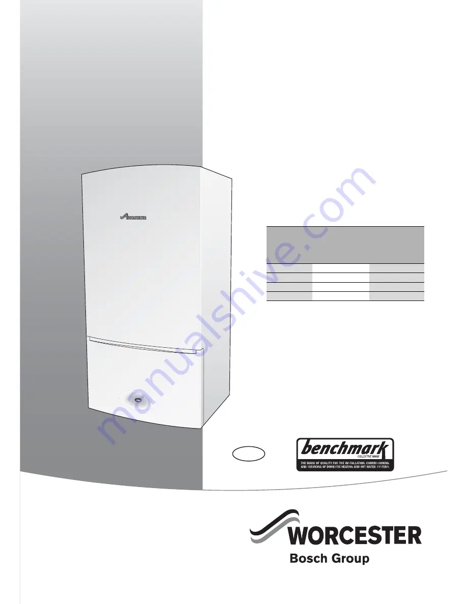
WALL HUNG RSF GAS FIRED CONDENSING SYSTEM BOILER

Greenstar i System Compact

6720646608-00.1W

o

FOR SEALED CENTRAL HEATING SYSTEMS AND INDIRECT MAINS FED DOMESTIC HOT WATER

6 72

0 807 726 (2013/05)

These appliances are for use with:

Natural Gas or L.P.G. 

(Cat. II 2H 3P type C13, C33 & C53)

Model

GC Number

Natural Gas

27i System Compact 41-406-13

30i System Compact 41-406-15

L.P.G.

27i System Compact 41-406-14

30i System Compact 41-406-16

Summary of Contents for 27i System Compact

Page 1: ...608 00 1Wo FOR SEALED CENTRAL HEATING SYSTEMS AND INDIRECT MAINS FED DOMESTIC HOT WATER 6 720 807 726 2013 05 These appliances are for use with Natural Gas or L P G Cat II 2H 3P type C13 C33 C53 Model GC Number Natural Gas 27i System Compact 41 406 13 30i System Compact 41 406 15 L P G 27i System Compact 41 406 14 30i System Compact 41 406 16 ...

Page 2: ...king for leaks during operation 35 5 6 Domestic hot water 35 5 7 Finishing commissioning 35 5 7 1 Replacing the boiler case 35 5 7 2 Securing the control panel 36 5 7 3 Fitting the fascia flap 36 5 7 4 Installing the bottom panel 36 5 7 5 Handover 36 5 7 6 Boiler guarantee 36 6 Service and spares 37 6 1 Inspection and service 37 6 2 Checking the gas inlet pressure 37 6 3 Checking flue integrity 38...

Page 3: ...c Cold Water Supply Electrical Supply Gas Supply Table 1 Commonly used symbols These instructions are applicable to the Worcester appliance model s stated on the front cover of this manual only and must not be used with any other make or model of appliance These instructions apply in the UK and Ireland only and must be followed except for any statutory obligations This appliance must be installed ...

Page 4: ...se or unauthorised modifications to the appliance flue or associated components and systems could invalidate the warranty The manufacturer accepts no liability arising from any such actions excluding statutory rights SERVICING Advise the user to have the system serviced annually by a competent qualified Gas Safe registered engineer Approved spares must be used to help maintain the economy safety a...

Page 5: ...c hot water 2 Wall mounting frame 3 Hardware literature pack Greenstar i System Compact Installation Commissioning and Servicing Instructions User guide Boiler fascia guide Wall mounting template Condensate connector Sealing Pack 4 PRV Installer connection elbow 5 Bottom panel 6 Fascia panel 690mm to top of case front 680mm 390mm 280mm 6720646609 01 2Wo 2 5 6 Depth to wall When fitted to wall fram...

Page 6: ...6 10 6 CO2 level at min rated heat output after 30 minutes 8 5 8 5 9 6 9 6 NOx class 5 5 5 5 NOx rating mg kWh 35 35 40 42 Condensate Maximum condensate rate l h 2 5 2 5 2 5 2 5 pH value approx 4 8 4 8 4 8 4 8 Electrical Electrical power supply voltage a c V 230 230 230 230 Frequency Hz 50 50 50 50 Maximum power consumption running W 102 108 102 108 Maximum power consumption stand by W 1 1 1 1 Gen...

Page 7: ... System Compact 6 720 807 726 2013 05 7 2 3 LAYOUT Fig 1 Main boiler components 6720646609 02 3Wo 43 42 41 40 39 38 37 36 35 34 26 49 48 47 46 44 45 29 28 27 30 7 31 33 8 32 13 9 10 11 12 1 2 3 4 5 6 15 16 17 18 19 22 23 21 24 25 14 20 ...

Page 8: ...ansion vessel connection point 21 Operation fault diagnostic light blue 46 Return temperature sensor NTC 22 Control panel flap 47 Gas valve 23 Boiler fascia guide location 48 Combustion air inlet 24 CH temperature control 49 Ignition transformer 25 Boiler display Table 4 Boiler components DHW temperature control The optional Integral Diverter Valve kit with cylinder sensor is required to enable th...

Page 9: ...ection of the gas supply to the boiler must be in accordance with BS6891 Under no circumstance should the size of the gas supply pipe be less than 22mmØ The meter or regulator and pipework to the meter must be checked preferably by the gas supplier This is to ensure that the equipment is in good working order and can meet the gas flow and pressure requirements in addition to the demand from any ot...

Page 10: ...OPTIONAL INTERNAL DIVERTER VALVE NOT SUPPLIED WITH BOILER 1 Diverter valve 2 Radiator valve flow 3 Lock shield valve return 4 Bypass 3 3 3 NEW INSTALLATIONS S PLAN PLUS LAYOUT NOTICE Artificially softened water must not be used to fill the central heating system The boiler is equipped with an internal by pass The internal bypass is not intended to be a substitute for an external system bypass An e...

Page 11: ...t such as an internal soil and vent stack internal kitchen or bathroom waste pipe washing machine waste pipe etc A suitable permanent connection to the foul waste pipe should be used Fig 6 Condensate pump disposal 3 4 2 EXTERNAL CONNECTIONS NOTICE Where a new or replacement boiler is being installed access to an internal gravity discharge point should beoneof thefactorsconsidered indeterminingboil...

Page 12: ...sed to prevent blockage by leaves may offer further protection from wind chill Pipe drainage will be improved if the end is cut at 45 as opposed to a straight cut Fig 8 External disposal Fig 9 Condensate pump to external disposal CONDENSATE SOAK AWAY The condensate drainage pipe may be run above or below the ground tothesoakaway Theexamplesshownonthispagerunaboveground The soak away must use a 100...

Page 13: ...removable door Minimum clearance required for servicing Height for either 60 100 flue or 80 125 flue 3 6 3 COMPARTMENTS Follow the requirements of BS6798 and BS5440 Part 2 and note Minimum clearances must be maintained An access door is required to install service and maintain the boiler and any ancillary equipment If fitting the boiler into an airing cupboard use a non combustible material to sep...

Page 14: ...ber 7 716 192 712 To cover the pipework under the boiler down to the counter top an optional Worcester accessory Below boiler pipe cover can be used Part number 7 716 192 608 Fig 14 Pipe dimensions Fig 15 Plumbing manifold Use the fittings supplied in the Hardware literature pack 2 Without the end wall zone 2 must extend 600mm from the bath Further guidance on pipe routing can be found printed on ...

Page 15: ...ture on a roof 600mm to room sealed flue or 1 500 to an open flue 15 200mm below eaves and 75mm below gutters pipe and drains 16 The dimension below eaves balconies and car ports can be reduced to 25mm as long as the flue terminal is extended to clear any overhang Any external flue joints must be sealed with suitable silicon sealant 17 Flue clearance must be at least 300mm from the ground Terminal...

Page 16: ...engths each 90 bend is equivalent to 2 metre of straight flue each 45 bend is equivalent to 1 metre of straight flue Plume management kits are available for the 60 100 horizontal flue system Part number 7 716 191 086 Refer to the manual supplied with the Plume Management kits for complete installation instructions i System boilers Maximum total flue length L mm FLUE TYPE 60 100 80 125 1 Telescopic...

Page 17: ...PRE INSTALLATION Greenstar i System Compact 6 720 807 726 2013 05 17 350 mm 570 mm 130 mm Min Flat roof 300 mm 500 mm Pitched roof 2 3 4 5 6 10 9 8 7 1 6720643895 12 1Wo ...

Page 18: ...t of the balcony or overhang 9 1 200mm from an opening in a car port on the same wall e g door or window leading into the dwelling 10 600mm distance to a surface facing a terminal unless it will cause a nuisance BS5440 Part1recommendsthatcareistakenwhensiting terminals in relation to surfaces facing a terminal 200 300 150 200 8 4 5 3 2 9 200 600 All measurements in millimetres 300 300 150 150 300 ...

Page 19: ...cludes the effective length of any bends plus the straight lengths The graph can be used to calculate Effective flue length if a specific effective plume length is required Effective plume length if a specific effective flue length is required Effective straight flue length with plume management Minimum plume length M 500mm Maximum plume length M 4 500mm Max flue length L 5 000mm Max flue length L...

Page 20: ...iler wall mounting template shows the relative positions of the flue and the top and bottom fixings of the wall mounting frame 1 Fix the wall mounting template to the wall in the desired position 2 Drill 4 holes for the wall mounting frame through the template REAR FLUE OUTLET The figure 22 shows the boiler wall mounting template with the flue centre lines of both the 100mm and 125mm flue systems ...

Page 21: ...6 Remove the inner packing 2 from the back of the boiler 7 Lietheboiler on the floor ensuring that the V shaped cardboard insert 8 is in place Fig 24 Finish unpacking REMOVING THE OUTER CASE Before the case can be removed the control panel must be moved into the service position i e hinged open 1 Remove the two screws underneath the fascia securing the control panel 2 Pull the catches forward to r...

Page 22: ... connector to the condensate drain pipe Fig 28 Condensate connection PRV PRE PLUMBING CONNECTION 1 Fit the PRV pre plumbing connector to the PRV locator bracket as shown in the figure below The elbow is supplied in the Hardware Literature pack Fig 29 PRV pipe connection Once the wall frame has been mounted the PRV discharge pipe can be fitted Fig 30 PRV elbow fitting Connect the PRV discharge pipe...

Page 23: ...el is shown removed for clarity Fig 33 Hanging the boiler Ensure that the gas and water connections to the isolating valves are made using the washers supplied in the Literature Hardware pack Tighten the gas and water connections firmly Connect the PRV discharge pipe on the hydraulic unit onto the PRV outlet pipework and hand tighten CAUTION Lifting the boiler There are two handling holes incorpor...

Page 24: ...TING THE SIPHON OUTLET 1 Push the black rubber siphon discharge hose onto the wall frame connector until fully engaged FILLING THE SIPHON 2 Pour 200 to 250 millilitres of clean water through the inner flue opening to fill the siphon before running the boiler Fig 35 Siphon fill 4 6 FLUE INSTALLATIONS HORIZONTAL FLUE 60 100mm diameter For vertical flues and 80 125mm horizontal flues please refer to ...

Page 25: ...ce the flue length further Fig 39 Further reduction Markthelengthrequiredfortheterminalasshown min 130mm and cut square taking care not to damage the tubes Remove any burrs and chamfer the edges of the tubes to assist ease of connection and prevent seal damage Push the terminal fully home into the turret and secure the terminal end with the screws 3 ensure that the TOP label is facing up 4 6 3 INS...

Page 26: ... the terminal ensuring that the clips 1 2 are engaged and secure 3 Loosen screws 3 and rotate the entire outlet assembly to redirect the plume Tighten screws 3 to secure in the required position Fig 44 Plume redirection Fig 45 Plume distance to opening 1 Opening in building 2 Flue discharge 3 Plume deflector 4 Minimum 1500mm from an opening in the building For more information refer to the 60 100 ...

Page 27: ...electrical supply The boiler is pre fitted with a mains supply cable External fuse rating 3 Amps 1 Low voltage connections 2 Mains voltage connections 3 Fuse carrier 5A 6720646609 44 1Wo 1 2 3 1 Low voltage terminal strip 1 Low voltage room thermostat input Not used 2 EMS bus connections 3 External cut off switch Not used 4 Outdoor compensation sensor 5 Cylinder sensor 6 Low Loss Header sensor Not...

Page 28: ...e cable will fit into the recess 3 in the control panel 2 Align the clips on the back of the Programmer Timer with the slots in the control panel Fig 50 Connecting the Programmer Timer 3 Push the Programmer Timer in to engage with the slots in the control panel 4 Pull the Programmer Timer down to secure with the clips 5 Slide the Installer access cover up into position 6 Secure with the three capt...

Page 29: ...his are single storey open plan dwellings where the livingareaismore than 70 of the total usable floor area Then this type of dwelling can be controlled as one zone Figures 52 and 53 give some suggestions regarding zoning the system for a small dwelling less than 150m2 using a third party programmer EXTERNAL 230V PROGRAMMER AND TWO HEAT ZONES WITH VENTED CYLINDER S PLAN PLUS For dwellings of less ...

Page 30: ...xternal components are connected to the Wiring centre junction box Fig 54 All of these points are wired to this point All of these points are wired to this point All of these points are wired to this point Table 11 Connection legend L E N 230V Mains Voltage Double Pole Fused Spur 6720646609 48 1Wo C Dual Thermostat N N M L N E M L N E E N L L N E 4 5 6 7 8 9 10 Heating Zone 1 Valve Cylinder Zone V...

Page 31: ...n cocks and drain the system while the boiler is hot Close drain cocks and add a suitable flushing agent at the correct strength for the system condition in accordance with the manufacturer s instructions Run the boiler system at normal operating temperature for the time stated by the manufacturer of the flushing agent Drain and thoroughly flush the system to remove the flushing agent and debris I...

Page 32: ...inthesystemshouldbe checkedevery12monthsor soonerifsystemcontent is lost The addition of sealing agents to the system water is not recommended as this can cause problems with deposits left in the heat exchanger FERNOX 0870 601 5000 www fernox com SENTINEL 0800 389 4670 www sentinel solutions net CAUTION RUNNING THE APPLIANCE Neverruntheappliancewhentheappliance systemis empty or partially filled 6...

Page 33: ...ncerning the current status of the boiler DuringnormalboileroperationvariousStatuscodescanbedisplayedby pressing the button The first screen of the Information menu displays the current Status code this will change as the boiler runs through various modes and sequences C F C F C F 6720807726 07 1Wo 2 s 1 2 3 eco C F N A 6720646608 31 1Wo SCREEN DISPLAY DESCRIPTION All possible screen symbols This ...

Page 34: ...the working pressure read at the meter minus 1mbar for natural gas or minus 2 5mbar for L P G Thepressuredropfromthemetertothegasvalvemustnotbemorethan 2 5mbar for natural gas or 4mbar for L P G If the pressure drop is greater than shown below then this would indicate a problem with the supply pipework which must be rectified Fig 61 Natural gas pressures NOTICE Thecombustionsettingsonthisgas fired...

Page 35: ...ervicemodethecontrolwillreturntonormaloperation after 15 minutes 5 5 4 CHECKING FOR LEAKS DURING OPERATION Use an approved leak detector to check all connections for possible leaks The product must be certified as a gas leak testing agent Do not allow the product to come into contact with the electrical wiring 5 6 DOMESTIC HOT WATER Controlling the hot water temperature The hot water temperature c...

Page 36: ...he installer gas emergency numbers Show the customer how to safely isolate the boiler Advise the customer where they can find information on the Worcester Bosch website Advisethecustomerthatthevaryingexternaltemperatureswillaffect the output of the boiler Ensure that the User Guide and Installation Commissioning and Service manual with the Benchmark checklist and service record is left with the bo...

Page 37: ...o the figures shown below Fig 67 Natural gas pressure Fig 68 L P G pressure CAUTION Mains supplies Turnoffthegassupplyandisolatetheelectricalmains supply before starting any work on the appliance and observe all relevant safety precautions CAUTION Component replacement After replacement of a gas related component where agasketorsealhasbeendisturbedorreplaced check for gas tightness using a gas sni...

Page 38: ...check that O2 is equal to or greater than 20 6 CO2 is less than 0 2 Ifthe readings are outside these limits thenthis indicates that there is a problem with the flue system or combustion circuit e g missing or dislodged seals Fig 70 Flue integrity test 6 4 COMPONENT ACCESS To gain access to the components remove the outer case 1 Remove the two screws securing the control panel 2 Release the two cat...

Page 39: ...ressure The pressure will read negative refer to the chart in the figure below Fig 74 Fan pressure readings If the manometer reading is in the white area of the chart the heat exchanger exhaust path siphon does not require attention If the manometer reading is in the black area of the chart then carry out the following checks Check that the siphon is not blocked Check the exhaust paths for restric...

Page 40: ... be removed to gain access to the heat exchanger for cleaning Lower the control panel into the service position Remove the case Disconnect electrical wires to the fan ignition transformer spark electrodes flue overheat thermostat main heat exchanger temperature sensor and flow pipe temperature sensor Flueway Fan assembly Ignition transformer Spark electrode assembly Burner housing burner and gaske...

Page 41: ...ingle bladed cleaning tool and brush Visually inspect the inside of the heat exchanger by shining a torch from the top down into the sump area When there is little or no light visible this would suggest that those channel s are restricted It is recommended that all channels are cleaned Remove the siphon and place a suitable container under the outlet to catch the water and debris Protect the contr...

Page 42: ... case 6 Release the two catches on top of the boiler 7 Pull the case towards you and remove Fig 82 Removing outer case On completion of the heat exchanger cleaning and re assembly perform the fan pressure test as described in section 6 5 2 CAUTION Mains supplies Turn off the gas supply and isolate the mains supplies before starting any work on the boiler and observe all relevant safety precautions...

Page 43: ... by pulling forward Replace the sensor onto the flow pipe Connect the lead to the sensor Re fit the combustion air inlet pipe to the pre mix unit Fig 85 Primary sensor 6 8 5 MAXIMUM SAFETY SENSOR Disconnect the lead to the maximum safety sensor 1 Remove the screw securing the sensor 2 Remove the sensor from the heat exchanger When replacing the sensor ensure that the assembly is properly located o...

Page 44: ...h the screw Tighten the bottom connection firmly with a suitable spanner Connect the top gas pipe Reconnect the electrical connector Open the boiler gas isolator Check all the gas connections for gas tightness 6 8 9 FAN ASSEMBLY Toremovethefan disconnecttheelectricalmainsandgassupplies and remove the following components Flueway Combustion air inlet pipe and gas pipe FLUEWAY REMOVAL Refer to figur...

Page 45: ...ngthe fan Fig 93 Fan removal 1 5 Rotate the exhaust pipe back to the right 6 Pull the fan assembly away from the mount lift and rotate the fan towards you Ensure that the front of the fan clears the left hand front castellated nut securing the burner housing 7 Pull the gas pipe off the fan body connection the pipe is secured by the interference fit between the pipe and connector Fig 94 Fan removal...

Page 46: ...lectrode gasket 1 Fig 97 Electrode assembly 6 8 13 BURNER HOUSING BURNER GASKET To remove the burner housing 1 Release and remove the four spring pins from the castellated nuts 2 Undo the front two castellated nuts springs and remove and retain along with the front two bolts 1 Slacken the two rear castellated nuts springs but do not remove Fig 98 Burner housing 3 Pull the burner housing up and for...

Page 47: ...hers 1 when replacing the heat exchanger Fig 101 Heat exchanger disconnection HEAT EXCHANGER REMOVAL Ensure any electrical wires or connectors are removed Remove the Auto air vent refer to section 6 8 7 to ease removal of the heat exchanger 1 Unscrew the heat exchanger retaining nut 2 Remove the heat exchanger retaining nut 3 Remove the two screws securing the heat exchanger to the air box 4 Lift ...

Page 48: ... wire connector from the bottom of the pump Fig 104 Pump head removal 6 8 17 PRESSURE GAUGE Ensure that the boiler is fully drained 1 Remove the securing screw and plate 2 Prise the lugs apart and remove the pressure gauge 3 Withdraw the spring clip from the pressure sensing head housing 4 Removethepressure sensing head andpressure gauge capillary from the housing Fig 105 Pressure gauge removal If...

Page 49: ...rom the bottom of the PRV 2 Pull the captive clip to the left to release the PRV 3 Pull the Central Heating pressure relief valve out of the housing Replace in reverse order secure with the clip and mounting screws Fig 108 PRV 6 8 21 HYDRAULIC BLOCK REMOVAL 1 Squeeze the ratchet connector and rotate clockwise to release 2 Release the clip on the expansion vessel connector at the pump assembly 3 Pu...

Page 50: ...CB FUSE The fuse is located next to the high voltage connectors and the spare fuse 1 is located on the back of the access cover To remove the fuse 1 Push the top of the fuse holder up 2 Rotate the top of the fuse holder anti clockwise and remove Fig 112 Fuse holder 6 8 24 REPLACING THE CONTROL UNIT With the installer access cover removed 1 Remove all the connectors 2 Slide out all the cable strain...

Page 51: ...The expansionvesselcanbereplaced withtheboiler inplaceifthereisa sideexitfluefittedandaminimumclearanceof450mmabovetheboiler casing If a vertical flue is fitted then a similar clearance to one side of the flue is required If the clearance is not available then the boiler will need to be removed from the mounting frame to gain access to the expansion vessel Alternatively a second vessel of at least...

Page 52: ...all frame by the bracket at the top Undo the two screws at the bottom of the case Release the clips at the top of the case and slide the case towards you to remove Disconnect the pipes and syphon discharge hose from the plumbing manifold Lift the boiler off the wall frame 1 Remove the screw retaining the expansion vessel to the wall frame 2 Remove the screw securing the right hand expansion vessel...

Page 53: ...00 28A 0 Burner seal 8 718 600 24A 0 Spark generator 8 718 688 015 0 Pump assembly 8 718 685 789 0 Flow NTC 8 718 688 801 0 Diverter valve assembly 8 716 106 845 0 Auto Air Vent T 005 000 87A 0 Pressure gauge 8 718 686 513 0 Diverter valve motor 8 718 682 839 0 Maximum safety sensor NTC 8 718 685 483 0 By pass valve 8 716 106 434 0 Expansion vessel 8 718 684 945 0 Pressure relief valve 3 bar 8 718...

Page 54: ... GAS VALVE SAFETY SOLENOID SAFETY SOLENOID PUMP CONTROL PUMP Purple White Black Fan wiring Live Brown Neutral Blue Fuse slow EMS BUS point HCM at rear of PCB Worcester 24V controls point F 5A H 230 V X7 X6 X5 X3 X11 X4 X12 DIAGNOSTIC INPUT DHW TEMPERATURE CONTROL CH TEMPERATURE CONTROL LCD DISPLAY Red Blue Red Blue Orange Blue Brown Black Green Orange Red G Y G Y G Y 6720646609 04 3Wo PRE WIRED LI...

Page 55: ...FAULT FINDING AND DIAGNOSIS Greenstar i System Compact 6 720 807 726 2013 05 55 7 2 HEATING FUNCTION Fig 118 Heating function ...

Page 56: ...FAULT FINDING AND DIAGNOSIS Greenstar i System Compact 6 720 807 726 2013 05 56 7 3 PROTECTION FUNCTIONS Fig 119 Protection function ...

Page 57: ...turn sensor disconnected 242to 256 F0 Internal error call Bosch help line 0844 892 3366 257 b7 Internal error replace control board 258 259 F0 Internal error call Bosch help line 0844 892 3366 260 No temperature rise after burner start 261 EA First Safety timing error 262 263 F0 Internal error call Bosch help line 0844 892 3366 264 C1 Airflow stopped during operation 265 Stand by mode forced due t...

Page 58: ...ing too fast 343 ED CH flue gas temperature rising but supply temperature not 344 ED HW flue gas temperature rising but supply temperature not 345 EF Supply and or return temperatures do not change after burner start 346 EC Flue gas temperature rising too fast 347 E3 Return temperature higher than supply temperature some time after burner start 348 EE HW supply temperature too hot 349 EF CH Boil D...

Page 59: ...35 μAmps i09 Flow temperature This is the actual temperature from the main heat exchanger displayed in real time i10 Maximum temperature This is the current temperature from the Maximum safety sensor This sensor is mounted on the front of the heat exchanger i13 Storage temperature The current temperature from the hot water cylinder sensor i14 Return temperature The current temperature returned to ...

Page 60: ... only visible when 2 1C is set to 0 and 2 1d is set to 1 Then the minimum pump speed can be set 2 1J Maximumpumpspeed pump speed at maximum burner load This parameter is only visible when 2 1C is set to 0 and 2 1D is set to 1 Then the maximum pump speed can be set 2 1E Pump energy saving mode 4 ON 5 OFF 2 2C Air purge mode This feature can be selected to purge the system and boiler of air 0 off 1 ...

Page 61: ...he button for at least 5 seconds to enter Menu 3 To modify a setting select desired menu option refer to table 18 via the and arrow buttons and press the OK button the option will flash Adjust the parameters using the and arrow buttons and press the OK button to confirm A symbol will be displayed for three seconds to confirm the update of the new value Fig 124 Menu 3 selection NOTICE Menu 3 Any ch...

Page 62: ...omponent to test Press the button the value 0 will flash Use the arrow button to change the value to a flashing 1 Press to confirm the change the value 1 will stop flashing and a will displayed for 3 seconds The test will run for 30 seconds or until the value is changed back to 0 Fig 127 Testing component ok max min max 2 3 1 0 4 bar 1 ok eco reset e C F Test 1 max min max 2 3 1 0 4 bar 1 ok eco r...

Page 63: ...seconds The spark will be audible if the igniter is OK t2 Fan test Checkingthebasicfan operation The fan will run for a maximum of 30 seconds If the fan is OK then the fan will be heard running t3 Pump test Checking the basic pump operation The pump will run for a maximum of 30 seconds If the pump is OK then the pump will be heard running t4 Three way valve test Test the operation of the diverter ...

Page 64: ...tton Incorrect HCM fitted 9U 233 HCM Heat Control Module Reset button Problem with the code plug faulty or not connected b7 257 Internal error Replace control board C6 215 Fan problem Reset button Fan running too fast 216 Fan problem Reset button Fan running too slow C7 214 Fan problem Reset button Fan not running 217 No airflow after a defined period of time Reset button Fan not running or airflo...

Page 65: ...onds before going to Locking error table 20 241 Return sensor disconnected Blocking for 300 seconds before going to Locking error table 20 D4 271 Temperature difference between flow and safety sensors exceeds limit The temperature of the primary flow and the safety sensor on the WB7 should be within 15 C of each other E9 224 MAX thermostat activated Flue gas thermostat overheat 276 Flow temperatur...

Page 66: ...ffect the customer s statutory rights If yes and if required by the manufacturer has a water scale reducer been fitted CONDENSING BOILERS ONLY The condensate drain has been installed in accordance with the manufacturer s instructions and or BS5546 BS6798 Yes If the condensate pipe terminates externally has the pipe diameter been increased and weatherproof insulation fitted Yes ...

Page 67: ...eer Name Company Name Telephone No Gas Safe Register No Comments Signature Date Engineer Name Company Name Telephone No Gas Safe Register No Comments Signature Date Engineer Name Company Name Telephone No Gas Safe Register No Comments Signature Date Engineer Name Company Name Telephone No Operative ID No Comments Signature Date Engineer Name Company Name Telephone No Gas Safe Register No Comments ...

Page 68: ...ster Bosch Group is a brand name of Bosch Thermotechnology Ltd worcester bosch co uk Document No 6 720 807 726 2013 05 WORCESTER BOSCH GROUP TECHNICAL SUPPORT 0844 892 3366 APPOINTMENTS 0844 892 3000 SPARES 01905 752571 LITERATURE 0844 892 9800 TRAINING 01905 752526 SALES 01905 752640 ...

Reviews: