Woodward ProTech TPS, Product Manual
Introducing the Woodward ProTech TPS, a cutting-edge industrial product designed to optimize performance and reliability. Enhance your understanding of this advanced technology and maximize its functionalities with our comprehensive Product Manual. Easily download your free manual from manualshive.com and unlock the full potential of the Woodward ProTech TPS.
Share
Download


Reviews:
No comments
Related manuals for ProTech TPS

WaveStar 2000A
Brand: PDi Pages: 107

CAEN-BLOCK-CENCN-2-POE
Brand: Crestron Pages: 2

GEK-45404F
Brand: GE Pages: 32

GEK-106465A
Brand: GE Pages: 43
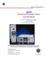
ALPS
Brand: GE Pages: 366

745 TRANSFORMER MANAGEMENT RELAY
Brand: GE Pages: 408

D90 Plus
Brand: GE Pages: 694

PDU3VN-Series
Brand: Tripp Lite Pages: 36

AG-0150
Brand: Tripp Lite Pages: 88

CPD-9
Brand: Citronic Pages: 2

VP7811B
Brand: Vertiv Pages: 79

Schroff 23147 - 005
Brand: Pentair Pages: 8

AL-CAT5W-4
Brand: l-com Pages: 5

PX2W
Brand: CHIEF Pages: 8

PSA-161
Brand: SHOWTEC Pages: 12

WB-800-IPVM-6
Brand: WattBox Pages: 16

Voltage Guard-70
Brand: Cristec Pages: 2

7M Series
Brand: Siemon Pages: 46


