background image

ADD MANUAL TITLE 

Wolf Steel Ltd., 24 Napoleon Rd., Barrie, ON, L4M 0G8 Canada / 103 Miller Drive, Crittenden, Kentucky, USA, 41030

Phone 1 (866) 820-8686 • www.napoleon.com • [email protected]

CERTIFIED TO THE CANADIAN AND AMERICAN NATIONAL STANDARDS: 

CSA 2.22 AND ANSI Z21.50 FOR VENTED DECORATIVE GAS APPLIANCES

INSTALLER: 

Leave this manual with the appliance

CONSUMER: 

Retain this manual for future reference

ADD PRODUCT CODE HERE (TRADE GOTHIC LT STD FONT)

NATURAL GAS MODELS:

PROPANE GAS MODELS:

Product Name / Code

(MUST use title from Price Book)

ADD ____ ILLUSTRATED

ADD PRODUCT IMAGE

CSA / 

INTERTEK

LOGO

SAFETY INFORMATION

- Do not store or use gasoline or other 
fl ammable vapors and liquids in the vicinity of 
this or any other appliance.

WHAT TO DO IF YOU SMELL GAS

:

• 

Do not try to light any appliance.

• 

Do not touch any electrical switch; do not 
use any phone in your building.

• 

Immediately call your gas supplier from a 
neighbour’s phone. Follow the gas    
supplier’s  instructions.

• 

If you cannot reach your gas supplier, call 
the fi re department.

- Installation and service must be 
performed by a qualifi ed installer, service 
agency, or the supplier.

This appliance may be installed in an aftermarket, 
permanently located, manufactured home (USA 
only) or mobile home, where not prohibited by 
local codes.

This appliance is only for use with the type of gas  
indicated on the rating plate. This appliance is 
not convertible for use with other gases, unless 
a certifi ed kit is used. 

FIRE OR EXPLOSION HAZARD

Failure to follow safety warnings exactly 
could result in serious injury, death, or 
property damage.

WARNING

!

ENGLISH 

$10.00

FOR INDOOR USE ONLY

IF INSTAL OPERATION, ADD SERIAL 

NUMBER LABEL HERE

IF SEPARATE MANUALS, ADD “PLACE 

BARCODE LABEL ON THE OWNER’S MANUAL”

INSTALLATION AND 

OPERATION MANUAL

GDS28-1NSB / GDS28-1NE / GS28-1N / GS28-1NE

GDS28-1PSB / GDS28-1PE / GS28-1P / GS28-1PE

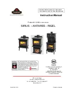
Haliburton™

(GDS28-1 illustrated)

SAFETY

 BARRIER

FRENCH

PG. 55

W415-2339 / B / 01.23.20

Model GS28 is made up of Model GDS28 and 

Natural Vent Adapter Kit GS-150KT

Summary of Contents for Napoleon Haliburton GDS28-1NE

Page 1: ... from a neighbour s phone Follow the gas supplier s instructions If you cannot reach your gas supplier call the fire department Installation and service must be performed by a qualified installer service agency or the supplier Thisappliancemaybeinstalledinanaftermarket permanently located manufactured home USA only or mobile home where not prohibited by local codes This appliance is only for use wit...

Page 2: ...t burns A physical barrier is recommended if there are at risk individuals in the house To restrict access to an appliance or stove install an adjustable safety gate to keep toddlers young children and other at risk individuals out of the room and away from hot surfaces Clothing or other flammable material should not be placed on or near the appliance Due to high temperatures the appliance should b...

Page 3: ...ase anemia those under the influence of alcohol those at high altitudes are more affected by carbon monoxide than others Failure to keep the primary air opening s of the burner s clean may result in sooting and property damage As with any combustion appliance we recommend having your appliance regularly inspected and serviced as well as having a Carbon Monoxide Detector installed in the same area t...

Page 4: ...ation 21 horizontal air terminal installation model GDS28 21 vertical air terminal installation 22 appliance vent connection 23 natural vent specifics 23 chimney installation 23 combustion air 23 installing natural vent 24 natural vent 24 adding vent sections 25 gas installation 26 optional wall switch remote millivolt 26 finishing 27 safety screen installation and removal 27 door closing and openi...

Page 5: ...ted This appliance may be installed in an aftermarket permanently located manufactured mobile home where not prohibited by local codes This appliance is only for use with the type of gas indicated on the rating plate This appliance is not convertible for use with other gases unless a certified kit is used This appliance is approved for bedroom and bed sitting room installations The protective wrap ...

Page 6: ...bathroom unless the unit is a direct vent sealed combustion product The installation must conform with local codes or in absence of local codes the National Gas and Propane Installation Code CSA B149 1 in Canada or the National Fuel Gas Code ANSI Z223 1 NFPA 54 in the United States Suitable for mobile home installation if installed in accordance with the current standard CAN CSA Z240MH Series for ...

Page 7: ...t resceller l évacuation après avoir executer l entretien du système de prise d air Serial Number N de Série W385 XXXX REFERENCE 161746 XXXX VENTED DECORATIVE GAS APPLIANCE NOT A SOURCE OF HEAT NOT INTENDED FOR USE AS A HEATING APPLIANCE NOT FOR USE WITH SOLID FUEL APPAREIL À GAZ DÉCORATIF À ÉVACUATION N EST PAS UNE SOURCE DE CHALEUR N EST PAS DESTINÉ À ÈTRE UTILISÉ COMME UN APPAREIL DE CHAUFFAGE ...

Page 8: ...n GAS LINE ACCESS HOLE LOCATED IN PEDESTAL BASE 26 3 4 680mm 22 1 2 572mm 11 1 4 286mm 7 178mm Ø AIR INTAKE 10 254mm 12 305mm 17 3 4 451mm 18 1 2 470mm 5 1 2 127mm 4 102mm Ø FLUE SAFETY BARRIER 1 3 4 44mm 1 5 dimensions front view right side view ...

Page 9: ...D 110 8 12 to 12 12 roof terminal kit GD 111 flat roof terminal kit GD 112 or periscope kit GD 180 for wall penetration below grade in conjunction with the appropriate venting components A terminal shall not terminate directly above a sidewalk or paved driveway which is located between two single family dwellings and serves both dwellings Local codes or regulations may require different clearances ...

Page 10: ...ner start up and or carboning Use an adjustable pipe as the final length of rigid piping to the stove for ease of installation These vent kits allow for either horizontal or vertical venting of the appliance The maximum allowable horizontal run is 20 feet 6 1m The maximum allowable vertical vent length is 40 feet 12 2m The maximum number of vent connections is two horizontally or three vertically e...

Page 11: ... 12 305mm above grade The maximum allowable vent length including both rise and run is 10 3m for a fireplace and 8 2m for a stove An insulation sleeve is illustrated in the top vent image below use only when supplied with the appliance The insulation sleeve is not required with a stove appliance 2 2 special vent installations 29 73 7cm Minimum 12 30 5cm Minimum to Grade 26 3 4 68cm 2 2 1 periscope ...

Page 12: ...rhang N 16 40 6cm 16 40 6cm Clearance above the roof O 2 0 6m 2 0 6m Clearance from an adjacent wall including neighbouring buildings P 8 2 4m 8 2 4m Roof must be non combustible without openings Q 3 0 9m 3 0 9m See chart for wider wall dimensions R 6 1 8m 6 1 8m See chart for deeper wall dimensions The terminal shall not be installed on any wall that has an opening between the terminal and the op...

Page 13: ...m of 40 feet 12 2m Horizontal run vertical rise to maximum of 40 feet 12 2m Vertical Termination For the following symbols used in the venting calculations and examples are greater than equal to or greater than less than equal to or less than HT total of both horizontal vent lengths Hr and offsets Ho in feet HR combined horizontal vent lengths in feet HO offset factor 03 total degrees of offset 90...

Page 14: ...T 0 9m V2 8 FT 2 4m VT V1 V2 3 FT 0 9m 8 FT 2 4m 11 FT 3 4m H1 2 5 FT 0 8m H2 2 FT 0 6m HR H1 H2 2 5 FT 0 8m 2 FT 0 6m 4 5 FT 1 4m HO 03 three 90 elbows 90 03 270 90 5 4 FT 1 7m HT HR HO 4 5 FT 1 4m 5 4 FT 1 7m 9 9 FT 3m HT VT 9 9 FT 3m 11 FT 3 4m 20 9 FT 6 4m Formula 1 HT VT 9 9FT 3m 11 FT 3 4m Formula 2 HT VT 40 FT 12 2m 20 9 FT 6 4m 40 FT 12 2m Since both formulas are met this vent configuratio...

Page 15: ...1 8m 16 7FT 5 1m Formula 1 HT 4 2 VT 4 2 VT 4 2FT 1 3m x 6FT 1 8m 25 2 FT 7 7m Formula 2 HT VT 24 75 FT 7 5m 16 7 FT 5 1m 24 75 7 5m Since both formulas are met this vent configuration is acceptable 90 V1 H1 H2 90 Example V1 4 FT 1 2m V2 1 5 FT 0 5m VT V1 V2 4 FT 1 2m 1 5 FT 0 5m 5 5 FT 1 7m H1 2 FT 0 6m H2 1 FT 0 3m H3 1 FT 0 3m H4 1 5 FT 0 5m HR H1 H2 H3 H4 2FT 0 6m 1FT 0 3m 1FT 0 3m 1 5FT 0 5m ...

Page 16: ...mple V1 5 FT 1 5m V2 6 FT 1 8m V3 10 FT 3 1m VT V1 V2 V3 5FT 1 5m 6FT 1 8m 10FT 3 1m 21FT 6 4m H1 8 FT 2 4m H2 2 5 FT 0 8m HR H1 H2 8FT 2 4m 2 5FT 0 8m 10 5 FT 3 2m HO 03 four 90 elbows 90 03 360 90 8 1 FT 2 5m HT HR HO 10 5FT 3 2m 8 1FT 2 5m 18 6FT 5 7m HT VT 18 6FT 5 7m 21FT 6 4m 39 6FT 12 1m Formula 1 HT VT 18 6FT 5 7m 21FT 6 4m Formula 2 HT VT 40 FT 12 19m 39 6FT 12 1m 40FT 12 2m Since both fo...

Page 17: ... HR H1 H2 6FT 1 8m 2FT 0 6m 8 FT 2 4m HO 03 four 90 elbows 90 03 360 90 8 1 FT 2 5m HT HR HO 8FT 2 4m 8 1FT 2 5m 16 1FT 4 9m HT VT 16 1FT 4 9m 4 5FT 1 4m 20 6 FT 6 3m Formula 1 HT 3VT 3VT 3FT 0 9m x 4 5FT 1 4m 13 5FT 4 1m 16 1FT 4 9m 13 5FT 4 1m Since this formula is not met this vent configuration is unacceptable Formula 2 HT VT 40 feet 12 2m 20 6FT 6 3m 40 12 2m Since only formula 2 is met this ...

Page 18: ...ntake flex liner and the exhaust collar must be connected to the exhaust flexible liner Both Simpson Duravent and Selkirk co linear to co axial adaptors have been approved on this appliance Follow vent manufacturer s installation instructions Different manufacturer s venting components must not be combined Once the preferred manufacturer s appliance adaptor has been attached the remainder of the sys...

Page 19: ...and intake vent pipe joints must be sealed using red RTV high temp silicone sealant W573 0002 not supplied or black high temp Mill Pac W573 0007 not supplied If using pipe clamps to connect rigid vent components a minimum of 3 screws must also be used to ensure the connection cannot slip off Do not clamp the flexible vent pipe Risk of fire explosion or asphyxiation Improper support of the entire ven...

Page 20: ... firestop top so that the vent shield covers the top of the vent within the opening Ensure that both spacer and shield maintain the required clearance to combustibles C Secure the spacer in place using the 4 longer screws supplied Once the vent pipe is installed in its final position apply sealant between the pipe and the firestop spacer The firestop assembly must be installed with the vent shield to ...

Page 21: ...ield and tighten This will prevent any materials such as insulation from filling up the 1 25mm air space around the pipe Caulking Vent Pipe Shield Vent Pipe Shield Vent Pipe Collar Firestop underside of joist A Stretch the inner flex pipe to the required length taking into account the additional length needed for the finished wall surface Apply a heavy bead of the red RTV silicone W573 0002 not suppl...

Page 22: ...ng over the air terminal connector leaving a min 3 4 19mm of the air terminal connector showing above the top of the flashing Slide the flashing underneath the sides and upper edge of the shingles Ensure that the air terminal connector is properly centered within the flashing giving a 3 4 19mm margin all around Fasten to the roof Do not nail through the lower portion of the flashing Make weather tight...

Page 23: ...ible on the exterior pipes once installation is completed An optional decorative black band may be available with this appliance In the event that the venting must be disassembled care must be taken to reseal the venting 2 50 8mm Overlap Mill Pac Sealant 8 X 1 2 Self Drilling Screws 3 3 natural vent specifics 3 3 1 chimney installation WARNING A chimney venting this appliance shall not vent any sol...

Page 24: ...ert the protective bushing Pull both spill switch wires through the bushing taking up any slack Replace the cover plate FOR MILLIVOLT Disconnect one of the black on off switch wires and attach to the other side of the terminal block Connect the remaining wires 1 black 1 white with 1 4 connectors to TP TH and TH on the gas valve FOR ELECTRONIC Disconnect one of the black on off switch wires connect...

Page 25: ...f the chimney extends more than 5ft 1 5m above the roof it must be secured using a roof brace or guide wires A raincap must be installed to avoid internal damage and corrosion 3 FT 1m MIN 3 FT 1m MIN 10 FT 3m OR MORE FLAT ROOF WALL RIDGE LESS THAN 10FT 3m 2 FT 0 6m MIN 3 FT 1m MIN 2 FT 0 6m MIN LESS THAN 10FT 3m 3 FT 1m MIN 2 FT 0 6m MIN 10 FT 3m TO NEAREST ROOFLINE Floor Ceiling Joist LIVING SPAC...

Page 26: ...ce is equipped with a manual shut off valve to turn off the gas supply to the appliance Connect the gas supply in accordance to local codes In the absence of local codes install to the current CAN CSA B149 1 Installation Code in Canada or to the current National Fuel Gas Code ANSI Z223 1 NFPA 54 in the United States When flexing any gas line support the gas valve so that the lines are not bent or k...

Page 27: ... slam or scratch Do not operate appliance with glass removed cracked or scratched Facing and or finishing material must never overhang into the appliance opening The glass door assembly is a safety device designed to pivot forward when relieving excess pressure that might occur Finishing or other materials must not be located in the opening surrounding the door as this will interfere with the doors...

Page 28: ...frame Snap the rear handle hook to lock the latch closed To open the door repeat in reverse order HINGE PIN BUSHING CATCH SLOT DOOR LATCH WARNING Glass may be hot Do not touch glass until cooled If equipped with door latches that are part of a safety system they must be properly engaged Do not operate the appliance with latches disengaged Before door is removed turn the appliance off and wait unti...

Page 29: ...curing process 1 3 4 Fig 1 WARNING Failure to position the logs in accordance with these diagrams or failure to use only logs specifically approved with this appliance may result in property damage or personal injury Logs must be placed in their exact location in the appliance Do not modify the proper log positions since appliance may not function properly and delayed ignition may occur The logs ar...

Page 30: ...osed to direct flame Use only certified glowing embers and PHAZER logs available from your local authorized dealer distributor WARNING Completely blocking the burner ports can cause an incorrect flame pattern carbon deposits and delayed ignition Randomly place the charcoal embers along the front and sides of the log support in a realistic manner Fine dust found in the bottom of the bag should not be ...

Page 31: ... located above the spill switch bracket on the adaptor D Venting action is satisfactory if the flame stays lit Venting action is unsatisfactory if the flame extinguishes E If venting action is unsatisfactory turn the appliance off wait 10 minutes and try again If the match does not stay lit turn the appliance off and check for vent blockage or restriction If necessary consult with a qualified inspect...

Page 32: ...before using the appliance Place near the IPI board If the back up is used it must be connected to this 6 volt battery pack supplied Do not connect to a 9 volt battery pack note PILOT W725 0062 NG W725 0063 LP GAS VALVE W750 0267 WIRE HARNESS W175 0633 CONNECTOR 885 PROFLAME MAIN ON OFF SWITCH W350 0702 BATTERY HOUSING BATTERY PACK W010 2763 NG W010 2808 LP PILOT ASSEMBLY W750 0274 POWER CORD APPL...

Page 33: ...ed I Turn on the remote wall switch to the appliance J If the appliance will not operate follow instructions TO TURN OFF GAS and call your service technician or gas supplier A Set thermostat to lowest setting if equipped B Turn off the remote wall switch to the appliance C Turn off all electric power to the appliance if service is to be performed D Turn manual shutoff valve clockwise to the OFF po...

Page 34: ...ill then begin the countdown for approximately seven days before shutting off the pilot if the appliance is not used This countdown will reset anytime the appliance main burner is used Therefore if the appliance is regularly used day to day the pilot will remain on However this system does not require the user to remember to turn the pilot off as summer approaches and avoids unnecessary fuel consu...

Page 35: ...t continue to burn repeat steps E through I J With pilot lit turn gas knob counter clockwise to the ON position K If equipped with the flame adjustment valve push and turn the knob to high L Turn on all electrical power to the appliance and re install the batteries into the transmitter if equipped Set thermostat to desired setting if equipped A Set thermostat to desired setting if equipped B Turn o...

Page 36: ...ith a soap and water solution Prior to pilot adjustment ensure that the pilot assembly has not been painted If overspray or painting of the pilot assembly has occurred remove the paint from the pilot assembly or replace Fine emery cloth or a synthetic scrub pad such as Scotch Brite can be used to remove the paint from the pilot hood electrode and flame sensor INSERT PILOT ASSEMBLY Maximum inlet pre...

Page 37: ...lifting from the burner ports The flame may not appear yellow immediately allow 15 to 30 minutes for the final flame colour to be established AIR SHUTTER ADJUSTMENT MUST ONLY BE DONE BY A QUALIFIED INSTALLER AIR SHUTTER OPENING VENTURI BURNER ORIFICE It is important that the orifice is securely inserted into the venturi note It s important to periodically perform a visual check of the pilot and burner...

Page 38: ...5 If your appliance is equipped with a safety barrier cleaning may be necessary due to excessive lint dust from carpeting pets etc simply vacuum using the brush attachment 6 If your appliance is equipped with relief doors ensure the system performs effectively Check that the gasket is not worn or damaged Replace if necessary 7 Replace the cleaned logs rocks or glass Failure to properly position th...

Page 39: ...uld be performed by a qualified service technician The firebox becomes very hot during operation Let the appliance cool completely or wear heat resistant gloves before conducting service Never vacuum hot embers Do not paint the pilot assembly WARNING Buff lightly with a clean dry soft cloth to remove accumulated dust or fingerprints Clean both sides of the glass after the first 10 hours of operation w...

Page 40: ... are neither pinched nor interfere with the blower operation Re secure the air intake manifolds INSTALLATION THROUGH THE FIREBOX REPLACEMENT BLOWER ACCESS GASKET IS REQUIRED Turn off the electrical power and the gas supply to the appliance Open the lower control door the two side doors and the fire viewing door Remove the logs Remove the blower access plate held on with 8 screws Disconnect the two ...

Page 41: ...y replacement parts a photocopy of the original invoice will be required to honour the claim When ordering replacement parts always give the following information Model Serial Number of appliance Installation date of appliance Part number Description of part Finish Parts part numbers and availability are subject to change without notice Parts identified as stocked will be delivered within 2 to 5 bu...

Page 42: ... GL 620 Left side log GL 620 W550 0001 W135 0061 12 13 11 10 5 6 7 8 9 Yes Glowing embers GL 620 W361 0016 Yes Yes ON OFF switch W660 0009 Trivet W010 2511 Yes Right side log GL 620 W135 0060 W715 0059 Rear log GL 620 Yes Yes Yes Yes 4 W475 6215 Control panel EI Ref No Part number Description 3 Ref No Part number Description GL 620 SAFETY BARRIER ASSEMBLY Items may not appear exactly as illustrate...

Page 43: ...100 0056 Main burner assembly W680 0008 Thermocouple Stocked Stocked Yes W010 0633 Pilot assembly NG w ignitor W290 0029 Pilot gasket W725 0042 Valve NG Yes Yes 14 14 14 14 14 14 14 14 14 12 13 14 14 10 14 11 1 2 3 5 6 7 14 4 14 8 14 9 4 3 5 7 6 1 9 10 11 12 2 Yes W010 0550 Pilot assembly P w ignitor Yes Yes 13 14 W290 0043 Burner gasket Yes W455 0052 Pilot orifice P Yes W455 0062 Pilot orifice NG W...

Page 44: ... orifice 54 P W456 0045 Burner orifice 45 NG W100 0056 Main burner assembly W455 0070 Pilot orifice 62 NG Stocked Stocked Yes W010 2763 Pilot assembly NG W290 0029 Pilot gasket W725 0062 Valve NG Yes Yes 14 14 14 14 14 14 12 13 13 14 11 14 11 1 2 2 3 2 3 5 4 1 10 11 11 12 2 Yes W010 2808 Pilot assembly P Yes Yes 13 13 W290 0043 Burner gasket Yes W455 0068 Pilot orifice 35 P 9 Yes W190 0176 Control mod...

Page 45: ...afety barrier assembly 1 Stocked 23 23 23 5 23 4 23 3 23 1 7 6 23 2 23 8 AR28SS W660 0081 Wall mounted thermostat F45 F60 Hand held remote control 6 3 3 GS328SSB Satin chrome plated door GS328KSB Metallic black door 4 GS200 SS Stain chrome plated ornamental trivet ANI K Black traditional andirons 5 2 Satin chrome plated accent bar 8 7 W361 0239 BULK Ambient glow embers ...

Page 46: ...heck that main burner is operating on HI AFTER TAKING PRESSURE READINGS BE SURE TO TURN SCREWS CLOCKWISE FIRMLY TO RESEAL DO NOT OVER TORQUE Leak test with a soap and water solution Air shutter improperly adjusted Return air shutter to specified opening see venturi adjustment section Carbon is being deposited on glass logs rocks media or combustion chamber surfaces Air shutter is blocked Ensure air...

Page 47: ...le Clean thermocouple and valve connection Replace thermocouple Replace valve Faulty valve Replace Pilot burning no gas to main burner gas knob is on HI wall switch thermostat is on Thermostat or switch is defective Connect a jumper wire across the wall switch terminals if main burner lights replace switch thermostat Wall switch wiring is defective Disconnect the switch wires connect a jumper wire...

Page 48: ...horting or faulty Loosen and tighten thermocouple Clean thermocouple and valve connection Replace thermocouple Main burner goes out pilot stays on Venting is spilling Test with spill switch bypassed Check for vent blockage GS28 Main burner goes out pilot goes out Vent re circulating Check joint seals and installation Main burner flame is a blue lazy transparent flame Blockage in vent Remove blockage...

Page 49: ...al DO NOT OVER TORQUE Leak test with a soap and water solution Air shutter improperly adjusted Return air shutter to specified opening see venturi adjustments section in the installation manual Carbon is being deposited on glass logs rocks media or combustion chamber surfaces Air shutter is blocked Ensure air shutter opening is free of lint or other obstructions Flame is impinging on the glass logs...

Page 50: ...ded Receiver if equipped Reset program hold reset button on receiver and wait for 2 beeps Release after second beep Press small flame button on remote within 20 seconds you will hear an additional beep this signals a successful reset Replace receiver Valve Check valve and replace if necessary Do not to overtighten thermocouple Burner continues to spark and pilot lights but main burner does not ligh...

Page 51: ...Choose one of the 3 methods below to reset the system 1 To reset ignition box when locked out Turn off power supply and remove batteries if used from the back up battery pack 2 To reset the DFC Board when the board goes into a lock out condition and the LED is blinking 3 times using the transmitter on off button Step 1 Turn the system off by pressing the on off button to turn the system off Step 2...

Page 52: ... caused by mechanical systems such as exhaust fans furnaces clothes dryers etc Any damages to the appliance combustion chamber heat exchanger plated trim or other components due to water weather damage long periods of dampness condensation damaging chemicals or cleaners will not be the responsibility of Napoleon During the first 10 years Napoleon will replace or repair the defective parts covered b...

Page 53: ... B 01 23 20 53 service history 18 0 service history Appliance Service History This appliance must be serviced annually depending on usage Date Dealer Name Service Technician Name Service Performed Special Concerns ...

Page 54: ...N NA A A A A A A A AP P P P P P P P PO O O O O O OL L L L L L L LE E E E E EO O O O O ON N N N C C C CE E EL L LE E EB BR RA AT TI IN NG G O OV VE ER R 4 40 0 Y YE EA AR RS S A A A O O O O O OF F F F F F H H H H H H H HO O O O O OM M M M ME E E E E C C CO OM M MF F FO OR RT T P PR RO OD DU UC CT TS S 7200 Route Transcanadienne Montréal Québec H4T 1A3 24 Napoleon Road Barrie Ontario Canada L4M 0G8 ...

Page 55: ...tallé dans une maison préfabriquée mobile déjà installée à demeure si les règlements locaux le permettent Cet appareil doit être utilisé uniquement avec le type de gaz indiqué sur la plaque d homologation Cet appareil ne peut être converti à d autres gaz sauf si une trousse de conversion est utilisée RISQUE D INCENDIE OU D EXPLOSION Incapacité à suivre ces avertissements exactement peuvent entraîn...

Page 56: ...brûlures accidentelles Une barrière de protection est recommandée si des individus à risque se trouvent dans la maison Afin de restreindre l accès à l appareil installez une barrière de protection ajustable pour garder les jeunes enfants ou autres personnes à risque hors de la pièce et loin des surfaces chaudes Les vêtements et autres matériaux combustibles ne doivent pas être posés sur l appareil ...

Page 57: ...eur s propre peut entraîner la formation de suies et dommages à la propriété Comme dans le cas de tout appareil à combustion il est recommandé de faire inspecter et entretenir votre appareil régulièrement De même installez un détecteur de monoxyde de carbone dans la pièce pour vous protéger ainsi que votre famille contre les intoxications pas applicable pour les appareils pour l extérieure Assurez...

Page 58: ...tions d évents 79 4 0 branchement du gaz 80 5 0 interrupteur mural télécommande optionnel millivolt 80 6 0 finitions 81 6 1 installation enlèvement de l écran de protection 81 6 2 ouverture et fermeture de la porte 82 6 3 disposition des bûches 83 6 4 braises incandescentes 84 6 5 braises de charbon 84 6 6 mise en place du logo 84 6 7 l enlèvement installation du couvercle d accès du contrôle 84 7...

Page 59: ...tion Cet appareil ne peut être converti à un autre type de gaz à moins d utiliser un ensemble de conversion certifié Cet appareil est approuvé pour installation dans les chambres à coucher et les chambres studio L emballage de protection sur les pièces s enlève mieux lorsque l assemblage est à température ambiante ou lorsqu il est chauffé à l aide d un séchoir à cheveux ou d une autre source de cha...

Page 60: ...imentation il doit être connecté à une réceptacle correctement mise à la terre La fiche de mise à la terre ne doit pas être retiré du cordon d alimentation Ce qui suit ne s applique pas aux foyers encastrés tant que les distances requises pour les dégagements aux matériaux combustibles sont respectées le meilleur endroit pour un appareil est le centre de la maison car ceci permet une meilleure util...

Page 61: ...manuel d installation pour des extensions plus grandes les longueurs d évacuation minimaux et maximum The appliance must be vented using the appropriate Napoleon vent kits See installation manual for venting specifications Proper reinstallation and resealing is necessary after servicing the vent air intake system L appareil doit être ventilé à l aide de l ensemble d évacuation propre à Napoleon Réf...

Page 62: ... 4 dimensions LE TROU D ACCÈS DE LA CONDUITE DE GAZ EST SITUÉ DANS LA BASE DU PIÉDESTAL Ø PRISE D A IR Ø BUSE 26 3 4 680mm 22 1 2 572mm 11 1 4 286mm 7 178mm 10 254mm 12 305mm 17 3 4 451mm 18 1 2 470mm 5 1 2 127mm 4 102mm 1 3 4 44mm ÉCRAN DE PROTECTION ...

Page 63: ...réinstallez le selon les instructions fournies dans l installation initiale Cet appareil doit être installé de manière à ce que le conduit d évacuation et de prise d air se prolongent sur toute la longueur de la cheminée Toute autre méthode d installation telle que d utiliser la cheminée comme partie du système d évent est interdite note Une terminaison ne doit pas être installée directement au de...

Page 64: ...rizontalement ou trois verticalement excluant les raccordements à l appareil et à la section de terminaison Lorsque vous utilisez les composants d évacuation Wolf Steel n utilisez que des composants d évacuation Wolf Steel conjointement avec les ensembles de terminaison suivants ensemble de terminaison murale GD 175 7 12 de conduits inclus ou ensemble de terminaison pour toit de pente 1 12 à 7 12 ...

Page 65: ...ur maximale permise de l évent comprenant l hauteur et la longueur est 10 pieds 3m pour une foyer et 8 pieds 2m pour une poêle Un manchon isolant est illustré dans l illustration ci dessous de l évacuation sur le sessus utiliser seulement lorsqu ils sont fournis avec l appareil Un manchon isolant n est pas requis avec une appareil poêle 2 2 installations particulières d évents 2 2 1 ensemble péris...

Page 66: ...rs adjacents incluant les maisons voisines P 8 2 4m 8 2 4m Le toit doit être incombustible et sans ouvertures Q 3 0 9m 3 0 9m Voir le tableau pour les dimensions d un mur plus large R 6 1 8m 6 1 8m Voir la tableau pour les dimensions d un mur plus profond La terminaison ne doit pas être installée sur quelconque mur ayant une ouverture entre la terminaison et le côté ouvert de la structure S 12 30 ...

Page 67: ...m La course horizontale la course verticale jusqu à un maximum de 40 12 2m Terminaison verticale Les symboles suivants sont utilisés dans le calcul et les exemples d évacuation plus grand que plus grand ou égal à plus petit que plus petit ou égal à HT total de la longueur des courses horizontales HR plus la valeur des déviations HO en pieds HR longueur des courses horizontales combinées en pieds H...

Page 68: ...R HO 4 5 PI 1 4m 5 4 PI 1 7m 9 9 PI 3m HT VT 9 9 PI 3m 11 PI 3 4m 20 9 PI 6 4m Formule 1 HT VT 9 9 PI 3m 11 PI 3 4m Formule 2 HT VT 40 PI 12 2m 20 9 PI 6 4m 40 PI 12 2m Puisque les deux formules sont respectées cette configuration d évacuation est acceptable Consultez le graphique pour déterminer la course verticale nécessaire VT par rapport à la course horizontale requise HT La section ombragée à...

Page 69: ...0 7PI 3 3m 6PI 1 8m 16 7PI 5 1m Formule 1 HT 4 2 VT 4 2 VT 4 2PI 1 3m x 6PI 1 8m 25 2PI 7 7m 10 7PI 3 3m 25 2 PI 7 7m Formule 2 HT VT 24 75 PI 16 7PI 5 1m 24 75 7 5m Puisque les deux formules sont respectées cette configuration d évacuation est acceptable Exemple V1 4 PI 1 2m V2 1 5 PI 0 5m VT V1 V2 4PI 1 2m 1 5PI 0 5m 5 5PI 1 7m H1 2 PI 0 6m H2 1 PI 0 3m H3 1 PI 0 3m H4 1 5 PI 0 5m HR H1 H2 H3 H4...

Page 70: ...2 HT VT 40 pieds 12 2m Exemple V1 5 PI 1 5m V2 6 PI 1 8m V3 10 PI 3 1m VT V1 V2 V3 5PI 1 5m 6PI 1 8m 10PI 3 1m 21 PI 6 4m H1 8 PI 2 4m H2 2 5 PI 0 8m HR H1 H2 8 PI 2 4m 2 5 PI 0 8m 10 5 PI 3 2m HO 0 03 quatre coudes 90 90 0 03 360 90 8 1 PI 2 5m HT HR HO 10 5PI 3 2m 8 1PI 2 5m 18 6 PI 5 7m HT VT 18 6PI 5 7m 21PI 6 4m 39 6 PI 12 1m Formule 1 HT VT 18 6PI 5 7m 21PI 6 4m Formule 2 HT VT 40 PI 12 2m 3...

Page 71: ...I 1 8m 2PI 0 6m 8 PI 2 4m HO 0 03 quatre coudes 90 90 0 03 360 90 8 1 PI 2 5m HT HR HO 8 PI 2 4m 8 1 PI 2 5m 16 1 PI 4 9m HT VT 16 1PI 4 9m 4 5PI 1 4m 20 6 PI 6 3m Formule 1 HT 3VT 3VT 3PI 0 9m x 4 5PI 1 4m 13 5 PI 4 1m 16 1 PI 4 9m 13 5 PI 4 1m Puisque cette formule n est pas respectée cette configuration d évacuation est inacceptable Formule 2 HT VT 40 pieds 12 2m 20 6 PI 6 3m 40 PI 12 2m Puisqu...

Page 72: ...accordé au conduit flexible de prise d air et le collet d évacuation de la terminaison au conduit flexible d évacuation Les adaptateurs colinéaire à coaxial Simpson Duravent et Selkirk sont approuvés pour cet appareil Suivez les instructions d installation du fabricant du système d évacuation Des composants d évacuation de différents fabricants ne doivent pas être combinés Une fois que l adaptateur ...

Page 73: ...onduits doivent être scellés avec du scellant de silicone rouge à haute température RTV W573 0002 non fourni ou du scellant noir à haute température Mill Pac W573 0007 non fourni à l exception du raccordement du conduit d évacuation à la buse de l appareil qui doit être scellé avec le scellant Mill Pac Si vous utilisez des colliers pour tuyau pour raccorder les composants d évacuation vous devez a...

Page 74: ...coupe feu et l écran protecteur conservent le dégagement nécessaire aux matériaux combustibles C Fixez en place l espaceur coupe feu à l aide des quatre vis longues fournies Une fois que le conduit d évent est en place appliquez du scellant entre le conduit d évent et l espaceur coupe feu L espaceur coupe feu doit être installé avec l écran protecteur orienté vers le haut La terminaison ne doit pa...

Page 75: ...onduit d évacuation Espaceur coupe feu face inférieure des solves C Dans le grenier faites glisser le collet de conduit d évacuation vers le bas afin de recouvrir l extrémité ouverte du protecteur de conduit d évacuation et serrez Ceci empêchera tout matériau tel que l isolant de remplir l espace vide de 1 po 25 4mm autour de l évent A Étirez la gaine flexible intérieure à la longueur requise en ten...

Page 76: ...us le connecteur de terminaison en laissant un minimum de 3 4 19 1mm de connecteur de terminaison visible au dessus du haut du solin Glissez le solin sous les côtés et le bord supérieur des bardeaux Assurez vous que le connecteur de terminaison est bien centré dans le solin en laissant une marge de 3 4 19 1mm tout autour Fixez le au toit Ne clouez pas à travers la partie inférieure du solin Imperm...

Page 77: ...tualité où le système d évents doit être démonté il faudra prendre soin de sceller les évents à nouveau Scellant à haute température 2 50 8mm chevauchement 8 X 1 2 vis autoperceuses 3 3 spécification pour le tirage naturel 3 3 1 installation de la cheminée AVERTISSEMENT Une cheminée servant d évacuation à cet appareil ne doit pas servir pour un appareil de chauffage à combustible solide Trois types...

Page 78: ...la plaque poinçonnée recouvrant les trous et placez les bagues de protection Sortez les fils des deux interrupteurs d écoulement par le trou de la bague en s assurant qu ils sont bien tendus Replacez la plaque d accès POUR MILLIVOLT Débranchez un des fils noir de l interrupteur puis attachez le sur l autre côté du bornier Branchez les fils restant 1 noir 1 blanc muni d un connecteur aux bornes TP TH ...

Page 79: ...5 1 5m elle devra être fixée au toit avec un support de toit ou des brides de sécurité Un chapeau de cheminée devra être installé afin d éviter des dommages internes et la corrosion 3 PI 1m MIN 3 PI 1m MIN 10 PI 3m OU PLUS TOIT PLAT MUR FAITE MOINS DE 10 PI 3m 2 PI 0 6m MIN 3 PI 1m MIN 2 PI 0 6m MIN MOINS DE 10 PI 3m 3 PI 1m MIN 2 PI 0 6m MIN 10 PI 3m LA LIGNE DE TOIT LE PLUS PRÈS ESPACE HABITABLE L...

Page 80: ...de 1 2 13mm Sans raccord flexible l appareil est conçu pour recevoir une conduite de gaz de 3 8 9 5mm L appareil est muni d une soupape d arrêt manuelle pour fermer l alimentation en gaz Branchez le gaz en conformité avec les codes locaux En l absence de codes locaux l installation doit être conforme au Code d installation du gaz CAN CSA B149 1 dans sa version pour le Canada ou le National Fuel Gas...

Page 81: ...z pas et n égratignez pas la porte vitrée Ne faites pas fonctionner l appareil lorsque la porte vitrée est enlevée fissurée brisée ou égratignée Les matériaux de façade ou de finition ne doivent jamais empiéter sur l ouverture de l appareil L assemblage de la porte est conçus pour pivoter vers l avant de l évacuation d un surplus de pression qui pourrait survenir Les matériaux de finition ou tout aut...

Page 82: ...TE Pour vous assurer que la porte est en position horizontale il sera peut être nécessaire de la soulever lorsque vous la fixez Pour ouvrir la porte suivez les instructions en sens inverse TIGE CHARNIÈRE BAGUE FENTE D ACCROCHAGE LOQUET 6 2 ouverture et fermeture de la porte AVERTISSEMENT La vitre peut être chaude Ne touchez pas la vitre jusqu à ce qu elle ait refroidi Les loquets de porte font part...

Page 83: ...2 3 4 NOTE Assurez vous que la patte de support gauche et les deux pattes de support droite sont plié vers le bas pour assurez que la flamme du brûleur avant n est pas aspiré en dessous du bûche avant Le cadre de l écran de braises a une distance d ajustment minimale Toutefois lorsque vous chauffez avec propane assurez vous que l écran de braise est sécurisé aussi proche à l arrière de la chambre d...

Page 84: ...raises incandescentes et bûches PHAZERMD disponible de votre détaillant autorisé locale AVERTISSEMENT Obstruez pas ni fermer les orifices du brûleur Le blocage des orifices du brûleur peut créer une flamme irrégulière des dépôts de carbone et un retard d allumage Éparpillez les braises à l avant et sur les côtés du support à bûches de façon à créer un effet réaliste N utilisez pas la fine poussière qu...

Page 85: ...upteur de sécurité pour éviter une accumulation de monoxyde de carbone ou une explosion de gaz non brûlés durant l allumage Si le tuyau de cheminée est bouché ou ne tire pas l interrupteur d écoulement coupera automatiquement l arrivée du gaz dans les 5 à 10 minutes qui suivent MODÈLE GS28 SEULEMENT VÉRIFICATION DU BON FONCTIONNEMENT DE L ÉVACUATION DOIT ÊTRE VÉRIFIÉ APRÈS L INSTALLATION DE L APPA...

Page 86: ...vegarde est utiliser il doit être connecté à cet pile de 6V fourni Ne branchez le pas à un pile de 9V note PILOT W725 0062 NG W725 0063 LP GAS VALVE W750 0267 WIRE HARNESS W175 0633 CONNECTOR 885 PROFLAME MAIN ON OFF SWITCH W350 0702 BATTERY HOUSING BATTERY PACK W010 2763 NG W010 2808 LP PILOT ASSEMBLY W750 0274 POWER CORD APPLIANCE GROUND STAR MAIN LINE W190 0176 CONTROL MODULE DISCONNECT THIS LE...

Page 87: ...il ne fonctionne pas suivre les instructions de couper l alimentation de gaz et puis appelez votre technicien de service ou fournisseur de gaz A Régler le thermostat à la réglage le plus bas si équipé B Tournez l interrupteur murale de l appareil à la position OFF C Coupez l alimentation électrique à l appareil si un travail d entretien doit être faites D Tournez le soupape fermeture manuelle vers...

Page 88: ...décompte se réinitialisera chaque fois que le brûleur principal de l appareil sera allumé Par conséquent si l appareil est utilisé régulièrement sur une base journalière la veilleuse restera allumée Ce système ne requiert donc pas que l utilisateur se souvienne d éteindre la veilleuse à l approche de l été évitant de consommer inutilement du combustible tout en demeurant prêt à être rallumé lorsqu...

Page 89: ...ition Gardez le bouton de contrôle du gaz enfoncé pendant une minute puis relâchez le Si la veilleuse ne reste pas allumée répétez les étapes E à I J Lorsque la veilleuse est allumée enfoncez et tournez le bouton de contrôle du gaz vers la gauche à ON K Si votre foyer est muni d une soupape d ajustement de la flamme tournez le bouton de contrôle à HIGH L Rétablissez l alimentation électrique à l ap...

Page 90: ...tuer le réglage de la veilleuse assurez vous que l assemblage de la veilleuse n a pas été peint S il y a des traces de peinture ou de surpulvérisation enlevez les de l assemblage de la veilleuse ou remplacez le Une toile d émeri ou un tampon récurage comme Scotch Brite peut être utilisé pour enlever la peinture sur la hotte de la veilleuse sur l électrode et sur la capteur de flamme INSERT PILOT AS...

Page 91: ...réréglée en usine selon le tableau ci dessous Indépendamment de l orientation du venturi plus le volet est fermé plus la flamme est jaune et aura tendance à causer des dépôts de carbone Plus le volet est ouvert plus la flamme est bleue et plus elle a tendance à se détacher des orifices du brûleur La flamme peut ne pas être jaune immédiatement allouez de 15 à 30 minutes pour que la couleur finale de la ...

Page 92: ...leur 5 Si votre appareil est fourni avec une écran de protection le nettoyage peut être nécessaire en raison d un excès de poussière peluches des tapis animaux etc utilisez un l attachement du brosse sur aspirateur pour nettoyer l écran 6 Si votre appareil est fourni avec les détendeur de portes assurez vous que le système fonctionne efficacement Assurez que le joint d étanchéité n est pas usé ou e...

Page 93: ...devrez nettoyer le capteur de flamme à l aide d une morceau de laine d acier ou un tampon récurage Scotch BriteMD afin de retirer toute trace d oxydation Nettoyez l assemblage du pilote à l aide d un aspirateur muni d une brosse souple Il est important de ne pas peinturer l assemblage de la veilleuse note Le caisson devient trés chaud lors du fonctionnement Laissez l appareil se refroidir compléteme...

Page 94: ...nnement de la soufflerie Réinstallez les collecteurs de prise d air INSTALLATION DEPUIS LA CHAMBRE DE COMBUSTION UN JOINT D ÉTANCHÉITÉ DE REMPLACEMENT POUR LA PORTE D ACCÈS DE LA SOUFFLERIE EST REQUIS Coupez l alimentation électrique et en gaz à l appareil Ouvrez la porte de contrôle inférieure les deux portes latérales et la porte vitrée Enlevez les bûches Retirez la plaque d accès de la soufflerie...

Page 95: ...ement de pièce sous garantie une photocopie de la facture originale sera requise afin de pouvoir honorer la demande Lorsque vous commandez des pièces donnez toujours l information suivante Modèle et numéro de série de l appareil Date d installation de l appareil Numéro de la pièce Description de la pièce Fini Pièces numéro des pièces et s il soit disponible peut changer sans préavis Parties identifi...

Page 96: ...W030 0022P W010 2464 3 2 1 5 7 9 10 6 12 13 14 15 19 17 19 19 20 21 8 11 16 4 4 19 19 19 18 19 19 22 23 19 24 W475 0779 SER Panneau de contrôle MV W390 0001 Loquet de porte X2 W380 0002 Interrupteur à vitesse variable seulement bouton GZ552 Soufflerie KB 35 Interrupteur à vitesse variable avec bouton Assemblage de la porte latérale X2 W010 2514 23 22 W690 0002 Capteur de chaleur W290 0045 Joint d é...

Page 97: ...680 0008 Thermocouple En stock En stock Oui Oui 14 14 14 14 14 14 13 14 11 12 1 14 2 3 5 6 7 8 14 4 14 9 10 4 3 5 7 6 1 9 10 11 12 2 Oui Oui Oui 13 14 Oui W455 0052 Injecteur de veilleuse P Oui W455 0062 Injecteur de veilleuse GN W680 0004 Thermopile Oui W725 0043 Soupape P Oui W010 0633 Assemblage de veileuse GN W290 0029 Joint d étanchéité du veilleuse W725 0042 Soupape GN Oui Oui Oui W010 0550 ...

Page 98: ...W100 0056 Assemblage du brûleur principal W455 0070 Injecteur de veilleuse 62 NG En stock En stock Oui W010 2763 Assemblage de veilleuse GN W290 0029 Joint d étanchéité de veilleuse W725 0062 Soupape GN Oui Oui 14 14 14 14 14 14 12 13 13 14 11 14 11 1 2 2 3 2 3 5 4 1 10 11 11 12 2 Oui W010 2808 Assemblage de veilleuse P Oui Oui 13 13 W290 0043 Joint d étanchéité du brûleur Oui W455 0068 Injecteur ...

Page 99: ...n W565 0195 SER 1 En stock AR28SS W660 0081 F45 F60 8 3 3 W361 0239 BULK GS200 SS GS328SSB GS328KSB 4 5 6 7 ANI K 2 Thermostat mural numérique Télécommande manuelle L écran de protection GS328 Andirons en fonte noir X2 Châssis de porte noir GS328 Châssis de porte plaqué chrome satiné GS328 Barre d accent Chrome satiné 23 4 23 8 Grille ornamentale plaquée chrome satiné Braises de foyer AMBIENT GLOW...

Page 100: ...rtie peut être vérifiée de la même façon en utilisant la vis B Le manomètre doit indiquer la pression comme décrit sur le diagramme ci dessous Assurez vous que le brûleur principal fonctionne à HI APRÈS AVOIR PRIS LA LECTURE DES PRESSIONS ASSUREZ VOUS DE TOURNER FERMEMENT LES VIS VERS LA DROITE POUR SCELLER NE SERREZ PAS TROP FORT Vérifiez pour des fuites en appliquant une solution d eau savonneuse ...

Page 101: ... secondes pour permettre au thermocouple de se refroidir Le système n est pas purgé correctement Purgez la conduite de gaz Plus de propane Remplissez le réservoir La flamme de la veilleuse n est pas assez puissante Augmentez la flamme de la veilleuse La flamme de la veilleuse n enveloppe pas le thermocouple Tournez légèrement la tête de la veilleuse pour améliorer la flamme autour du thermocouple Le t...

Page 102: ...GDS28 SYMPTÔME PROBLÈME SOLUTIONS La porte se coince La poussiére saleté adhère aux charnières elle est chauffée et brûle coinçant ainsi la porte Enlevez la porte des charnières en la soulevant Lubrifiez les charnières avec du graphite Replacez NOTE Étant donné que les charnières sont exposées à des températures élevées des lubrifiants liquides tels que de l huile ou du WD 40 les feraient gripper Le...

Page 103: ...uites en appliquant une solution d eau savonneuse Le volet d air est réglé incorrectement Voir la section réglage du venturi pour le réglage de l ouverture du volet d air dans le manual d installation Du carbone se dépose sur la vitre les bûches les roches les composants décoratifs ou les parois de la chambre de combustion Le volet d air est bloqué Assurez vous que l ouverture du volet d air n est...

Page 104: ...erte Vérifiez si la pression d arrivée est dans les limites acceptables La pression d arrivée ne doit pas excéder 13 de colonne d eau 32 4mb Plus de propane Remplissez le réservoir La ligne d alimentation de la veilleuse peut contenir l air Répétez le processus d étincelles plusieurs fois ou purger la conduite d alimentation de la veilleuse Le module n est pas mis à la terre Assurez le bon polarité...

Page 105: ... si équipé Vérifiez que le récepteur est dans la position milieu La télécommande ne fonctionne pas Vérifiez les pile ainsi que leur orientation Le guide suivant est pour le système de SIT seulement La veilleuse ne s allume pas Aucun bruit et aucune étincelle au brûleur de la veilleuse Les lumières et la souffle rie fonctionnent si équipé La boîte d allumage a été verrouillée Choisissez l une des troi...

Page 106: ...es périodes d humidité la condensation des produits chimiques ou produits d entretien nuisibles ne seront pas la responsabilité de Napoléon Durant les dix premières années Napoléon remplacera ou réparera les pièces défectueuses qui sont couvertes par la garantie à vie limitée à sa discrétion gratuitement Après les dix premières années Napoléon fournira les pièces de rechange à 50 du prix de détail...

Page 107: ... 20 107 garantie FR 18 0 historique d entretien Historique de service de l appareil Cet appareil doit être entretenu annuellement selon son usage Date Détaillant Nom du Technicien Travail Effectué Problèmes Particuliers ...

Page 108: ...L LU US S D DE E 4 40 0 A AN NS S D D E EXISTENCE C C C C C CO O O O O ON N N N N N N N NS S S S S SA A A A A AC C CR R R R RÉ É É ÉS S À À À L L LA A C CO ON NC CE EP PT TIO ON N D DE PR RODUITS DE CONFORT 7200 Route Transcanadienne Montréal Québec H4T 1A3 24 Napoleon Road Barrie Ontario Canada L4M 0G8 214 Bayview Drive Barrie Ontario Canada L4N 4Y8 103 Miller Drive Crittenden Kentucky USA 41030 ...

Reviews: