background image

wodtke 

Pellet


Primärofen

®

 - Technology 


Assembly and Operating Instructions 
Control S5 


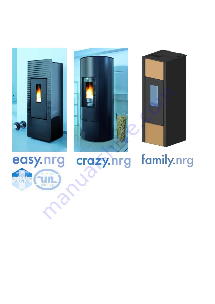
Ofentyp PO 03-2 "easy.nrg

®


", PO 03-5 "crazy.nrg" and PO 03-7 "family.nrg


", Airplus from software S5 007 

 
Thank you for deciding to purchase our product. Please be sure to read the instructions before 
installing and commissioning your furnace. By doing so, you will prevent damages which can be 
caused by improper installation or operation. Your furnace will reward you and the environment 
with optimal functionality. 
 
We wish you cozy warmth and many comfortable hours with your wodtke Pellet Primärofen fur-
nace. 
 
Sincerely, wodtke GmbH 


Summary of Contents for Primarofen PO 03-2 easy.nrg

Page 1: ...to purchase our product Please be sure to read the instructions before installing and commissioning your furnace By doing so you will prevent damages which can be caused by improper installation or op...

Page 2: ...Panelling of family nrg 15 7 Placement of the Furnace 18 8 Electrical Connection Cabling 18 8 1 Connector Block 19 8 2 Internal Wiring Diagram 20 8 3 Main Board Inputs 21 8 4 Main Board Outputs 25 9...

Page 3: ...rts 49 16 12 Completion of Maintenance Work Test Run and Maintenance Reset 50 17 Menu Level Unit Data Query 51 17 1 Output of Operating and Collective Fault Messages Relay Table 52 18 Fault Analysis F...

Page 4: ...uction In the case of improper in terventions all warranties and guarantees are void See also the chapter Proper Use During final acceptance the specialist company must always instruct the operator of...

Page 5: ...during in stallation and before operation By doing so you will prevent malfunctions and operating errors 1 The heating demand can be estimated at 0 15 KW m of living space for buildings from before 1...

Page 6: ...price list Solid fuels such as wood pellets require more time for ignition than liquid or gaseous fuels The ignition process leading to the first flame al ready requires several minutes and the furna...

Page 7: ...ve to the outside occur in the installation room and that the re quired combustion air approx 25 m3 h is additionally supplied for the heating system 3 5 Chimney Connection A chimney calculation must...

Page 8: ...sarily lead to deviations in different systems For example this means that a doubling of the ash content from 0 25 to 0 5 will also result in a doubling of the cleaning and mainte nance frequency 2 Th...

Page 9: ...simple reliable and sturdy design without additional drive units and motors With the Vario the pellet connection can also be closed and the furnace can be separated from the storage facility for main...

Page 10: ...r manually unload transport the pallet from the vehicle For manual transport always first release furnace from the pallet Proceed carefully and ensure that the feet of the furnace do not fall between...

Page 11: ...slats 7 pieces on the top side of the unit Fig 3 easy nrg slats 2 Lift the front decorative panel shown in white upward out of the guide 1 and remove toward the front 2 Fig 4 front decorative panel r...

Page 12: ...Panelling 1 Remove the front decorative pane see Chapter 6 1 1 on page 11 2 Unscrew the fastening screws Fig 8 3 Remove the 6 screws on the rear side Fig 9 4 Tilt the side walls laterally and remove...

Page 13: ...nect the control board cable from the control board cable is clipped see Fig 12 Fig 12 control board cable connection 6 2 2 Side Panel Removal 1 Open the door with the enclosed socket hex handle and r...

Page 14: ...rews per side on the front Fig 17 and Fig 18 Fig 17 unscrew front top fastening screws Fig 18 unscrew front bottom fastening screws 3 The side panels can now be removed To do so tilt the panel out in...

Page 15: ...ct control board cable on the right hand side cable is clipped and remove cover Fig 21 Cover Removal 6 3 2 Remove Front Top Front Bottom Panelling 1 Open combustion chamber door 2 Remove the fastening...

Page 16: ...76 6 3 3 Remove Left Right Side Panels The front top and bottom panels must first be re moved see Chapter 6 3 2 1 Loosen but do not unscrew the 6 screws for the side panels on the rear side Fig 24 Fig...

Page 17: ...rinted 04 2015 Part No 950 976 3 Pivot side panel out to the left or right and re move upward Fig 26 Fig 26 Remove Side Panelling 6 3 4 Remove Rear Top Bottom Panel ling 1 Loosen do not unscrew the sc...

Page 18: ...li cable local technical rules particularly the VDE guidelines No liability is accepted for damage to the unit due to improper connections and any war ranty is void No electrical connection cables fro...

Page 19: ...n board accessible the left hand panel of the unit must be removed If the Input RS 485 or BB S5 connections are used Chapters 8 3 3 and 8 3 6 the front panel must be removed Fig 29 central connector b...

Page 20: ...ate open Grate closed Control board Boiler sens intern Output sensor Unit internal switch monitoring functions Digital inputs internal 24V DC supply Caution Voltage Disconnect power plug before workin...

Page 21: ...y PC Tool 2 Fig 33 main board inputs Never connect 230 V to these inputs as this will damage the board Min Max On Off and Re serve inputs are protected against polarity rever sal If an external contro...

Page 22: ...tion input Priorities I O button has first priority MIN MAX external ON OFF external R M internal have priority over modulation If the modulation input is switched active the fur nace no longer respon...

Page 23: ...cator appears in the display the RS 485 input bus communication is now switched active Press button for at least 3 seconds return to operating level Currently only the Paradigma Systa Comfort is avail...

Page 24: ...furnace only operates if the Reserve input is closed no later than after 15 seconds It is then permanently monitored during operation whether the bridge is closed If the bridge is opened during opera...

Page 25: ...ation Note G OFF applies as operation Output R1 OFF 0 V furnace off or fur nace not ready e g voltage failure fur nace shut down via button or furnace shut down via external internal control ler 8 4 4...

Page 26: ...port screw automatically deliv ers the correct volume of fuel according to the se lected heating output The air required for com bustion flows to the burner pot in a controlled man ner The gases combu...

Page 27: ...wer Burner pot cast Igniter element Inlet pipe with air volume sen sor LMS Exhaust fan Foot STB main fuse 5A fast furnace rear side Connection of ex ternal pellet loader rear Decorative glass Cast gra...

Page 28: ...STB and fuse The safety temperature limiter is a mandatory safety device which shuts off the device in case of excessive overheating and must then be manually released again The STB is located on the...

Page 29: ...e air volume sen sor If this temperature is above the target value the unit is switched to fault The same occurs if the temperature rises too quickly gradient 9 5 Pellet chute temperature sen sor TP A...

Page 30: ...cm Minimum clearance outside the radiation area and outside the area of hot air outlets to the rear 20 cm to the sides 15 cm D Minimum clearance of flue pipe to flammable components ac cording to spec...

Page 31: ...t rather led vertically behind the furnace the vertical part of the flue pipe must have a minimum clearance of 5 cm to the rear wall of the furnace dimension E If the flue pipe is run through a wall w...

Page 32: ...lets in a timely manner Turn the rotary handle of the pellet drawer if pre sent until it opens Then open the pellet drawer Fig 56 opening pellet drawer Fill pellets up to the lower edge of the seal Cl...

Page 33: ...he burner pot too late Proceed as described below in order to prevent this This process takes approx 3 4 minutes and must also be repeated if the pellet container A has run completely empty Proceed as...

Page 34: ...ting permit Always keep combustion chamber door closed even when in a cold state Never use combustible or highly flammable liq uids for igniting The door with the ceramic glass pane be comes very hot...

Page 35: ...lowing indi cators appear OFF furnace switches off G OFF fan stop delay 15 minutes Stand By Dot Preselect output Press or button until the desired heating output H is set The heating output is adjuste...

Page 36: ...ntly the furnace returns to the heating programme H R 120 CLEANING PROGRAMME R indication of remaining duration in seconds An automatic cleaning cycle of 120 seconds is started after each hour of cont...

Page 37: ...w output depending on the pellet quality and output set tings of the unit This is a natural process during the combustion of wood pellets and is not a de fect Caution Before beginning cleaning mainten...

Page 38: ...x for this purpose Fig 64 window coating Fig 65 ash in the combustion chamber Embers remaining in the ash represent a fire hazard Only vacuum ash into a vacuum cleaner bag if you are absolutely certai...

Page 39: ...grate and ash drawer may still be hot or contain embers Risk of fire The furnace may never be operated without the cast grate The cast grate may not be removed pulled during operation of the furnace...

Page 40: ...C Fig 72 cross section grate and burner pot 15 5 Cleaning Surfaces Powder coated surfaces should be wiped with a damp cloth do not scrub Do not use scouring agents or acidic alkaline cleaning agents S...

Page 41: ...characteristic for maintenance frequency Quality pellets generally have only about 0 2 to 0 3 ash content Regularly clean the burner pot We recommend having maintenance performed by a qualified insta...

Page 42: ...aner we recommend our Ash Box as the attachment Screwdriver Phillips head socket and fork wrench set Pliers Paint brush Do not perform maintenance work until the unit is in Stand By mode and the fan s...

Page 43: ...with curvature warping Fig 74 cracked grate 2 Check the vertical distance A between the burner pot and the cast grate Fig 75 The distance may not be greater than 1 mm Adjust gap clearance as required...

Page 44: ...over screws 3 Pull out all 12 turbulators upward out of the heating gas flues and clean with a cloth Fig 80 turbulators Fig 81 turbulator removal and cleaning 4 Thoroughly clean all 12 heating gas flu...

Page 45: ...ired significant warping damage wear Fig 83 top ash chamber Important Ensure that the box in the upper area sits as far forward as possible Fig 83 Fig 84 box in ash chamber 6 Clean the heating gas col...

Page 46: ...d the front Fig 88 3 Then perform cleaning the same as for the family nrg Chapter 16 3 from step 3 Fig 87 easy nrg without front bezel Fig 88 removal of cast cover 16 5 Cleaning Heating Gas Flues craz...

Page 47: ...nner screws with rubber dampers Important Only clean flue gas fan when it has been removed in order to prevent damage Fig 90 fan screws 2 Clean all fan impellers with a rag or brush Caution Do not ben...

Page 48: ...a paint brush if necessary Attention Never clean air volume sensor with scouring brushes etc This would destroy the sensor s electronics Always remove air volume sensor LMS com pletely with the carrie...

Page 49: ...rticular cables may not be in stalled over sharp edges or hot spots and may not have cracks blank spots Replace cables in case of breakage cracks etc Carefully dust electrical components with a paint...

Page 50: ...s document Our tip Have you really completely and uniformly cleaned the combustion chamber heat exchanger all heating gas flues flue gas fan and connector Maintenance was only successful if the flue g...

Page 51: ...TL Air volume sensor temperature in C Indicates the combustion air temperature currently meas ured by the LMS in the air intake pipe TR Flue gas temperature in C Indicates the combustion temperature c...

Page 52: ...ay R1 ON R2 Collective fault message R2 0 V fault Display R2 OFF R2 230 V no fault Display R2 ON R4 potential free operating message monitored safety relay as normally closed R4 closed furnace off Dis...

Page 53: ...e pressed once per error Reset acknowledge error that is press I O button 2x in the case of 2 errors Fault code Class 1 Cause of fault Target values Resolution of fault TL HI air volume sensor temper...

Page 54: ...nite Empty pot first See to the right Case 2 cause Shut down in opera tion because there aren t enough pel lets in the storage container or container has run empty there are only a few pel lets in the...

Page 55: ...e input serves for feedback from ex ternal accessories It is verified 15 seconds after each start whether this input is bridged that is closed Only then does the unit go into the heating programme The...

Page 56: ...reference temperature sensor of main board Replace main board HP Er3 Main board EEPROM write read error Data cannot be correctly read one time transfer error when writing reading data to EEPROM of ma...

Page 57: ...hutdown HE OFF G OFF BU ER1 Bus communication with external heating con troller disrupted for longer than 60 seconds or external heating controller gateway incor rectly connected defective or RS 485 i...

Page 58: ...ifications to the air volume by a specialist company are required Multiple connection connection to common chimney Additional safety equipment is required when connecting Pellet Prim rofens to chimney...

Page 59: ...s Reserved Printed 04 2015 Part No 950 976 20 Dimensions 20 1 Dimensions of PO 03 2 easy nrg Fig 96 PO 03 2 dimensional drawing Option Vario pellet gate top bottom connection Connection dimensions mm...

Page 60: ...GmbH T bingen All Rights and Changes Reserved Printed 04 2015 Part No 950 976 20 2 Dimensions of PO 03 5 crazy nrg Fig 97 PO 03 5 dimensional drawing Option Vario pellet gate top bottom connec tion C...

Page 61: ...1 68 Wodtke GmbH T bingen All Rights and Changes Reserved Printed 04 2015 Part No 950 976 20 3 Dimensions of PO 03 7 family nrg Fig 98 PO 03 7 dimensional drawing Option Vario pellet gate Connection d...

Page 62: ...Manual_S5_Airplus_2015_04_20 Page 62 68 Wodtke GmbH T bingen All Rights and Changes Reserved Printed 04 2015 Part No 950 976 21 Declaration of Performance...

Page 63: ...Manual_S5_Airplus_2015_04_20 Page 63 68 Wodtke GmbH T bingen All Rights and Changes Reserved Printed 04 2015 Part No 950 976...

Page 64: ...Manual_S5_Airplus_2015_04_20 Page 64 68 Wodtke GmbH T bingen All Rights and Changes Reserved Printed 04 2015 Part No 950 976...

Page 65: ...h ordinary impurities normal relative humidity dry rooms according to VDE 0100 and with room temperatures from 5 C to 30 C envi ronmental temperatures during operation The installation room or combust...

Page 66: ...Any damage due to mechanical chemical or thermal overload electrical overload as well as defects due to faulty operation or improper installation handling use cleaning maintenance or operation in part...

Page 67: ...ill also inform and support you regarding all other questions about your wodtke Pellet Prim rofen If you should ever have a problem with your unit or are unable to resolve faults please contact your s...

Page 68: ...We wish you cozy warmth and many comfortable hours with your wodtke Pellet Prim rofen furnace Sincerely wodtke GmbH wodtke GmbH Rittweg 55 57 D 72070 T bingen Hirschau Tel 0 70 71 70 03 0 Fax 0 70 71...

Reviews: