background image


WIPLINE FLOATS • SKIS • MODIFICATIONS • AIRCRAFT SALES 
AVIONICS  • INTERIOR  •  MAINTENANCE •  PAINT REFINISHING 

1700 Henry Ave – Fleming Field (KSGS), South St. Paul, MN 55075 


Ph: 651.451.1205   Fax: 651.457.7858 

www.wipaire.com 


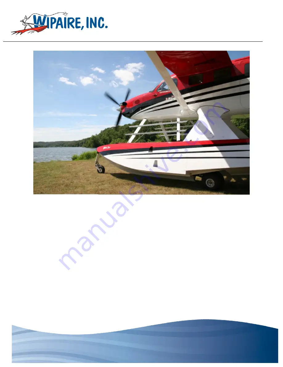
SERVICE MANUAL & ICA 

for the 

WIPLINE 7000 AMPHIBIAN FLOAT 

on the 

QUEST MODEL 100 KODIAK

Summary of Contents for WIPLINE 7000

Page 1: ...SALES AVIONICS INTERIOR MAINTENANCE PAINT REFINISHING 1700 Henry Ave Fleming Field KSGS South St Paul MN 55075 Ph 651 451 1205 Fax 651 457 7858 www wipaire com SERVICE MANUAL ICA for the WIPLINE 7000 AMPHIBIAN FLOAT on the QUEST MODEL 100 KODIAK ...

Page 2: ...SERVICE MANUAL I C A FOR THE 7000 AMPHIBIOUS FLOATS Revision G Page 2 of 102 P N 1004646 Doc No W7001 24 01 THIS PAGE INTENTIONALLY LEFT BLANK ...

Page 3: ...en Grease as an approved grease 4 18 2013 G See List Updated Fig 1 6 for new oleo updated Fig 4 4A Fig 4 6 and added 4 4B Changes to MLG rigging procedures remaining paged repaginated minor changes to float install and removal instructions 5 30 2014 H See List Added shear torque chart PR 1440 C Sealant and Tef Gel removed warranty claim form Corrected 1200 was 1000 1400 was 1150 and 1900 was 1300 ...

Page 4: ...SERVICE MANUAL I C A FOR THE 7000 AMPHIBIOUS FLOATS Revision G Page 4 of 102 P N 1004646 Doc No W7001 24 01 THIS PAGE INTENTIONALLY LEFT BLANK ...

Page 5: ...US FLOATS Revision K Page 5 of 102 P N 1004646 Doc No W7001 24 01 LIST OF EFFECTIVE PAGES PAGES REVISION PAGES REVISION PAGES REVISION 1 102 D Cover page 3 5 7 73 106 E 3 5 79 F 5 7 9 21 45 110 G 3 5 63 82 85 H 3 5 22 82 90 96 107 J 3 5 73 80 K ...

Page 6: ...SERVICE MANUAL I C A FOR THE 7000 AMPHIBIOUS FLOATS Revision G Page 6 of 102 P N 1004646 Doc No W7001 24 01 THIS PAGE INTENTIONALLY LEFT BLANK ...

Page 7: ...IRWORTHINESS LIMITATIONS 25 CHAPTER 3 NOSE GEAR 29 3 0 NOSE GEAR 29 3 1 ADJUSTMENT TEST NOSE GEAR 31 3 2 NOSE GEAR BASIC SERVICING 32 3 3 NOSE GEAR DISASSEMBLY 33 3 4 NOSE GEAR ASSEMBLY 34 CHAPTER 4 MAIN LANDING GEAR BRAKES GEAR RETRACTION 37 4 0 GENERAL 38 4 1 MAIN GEAR RETRACTION DESCRIPTION 41 4 2 MAIN GEAR ASSEMBLY SETUP AND ADJUSTMENT 48 4 3 ADJUSTING THE GEAR UP POSITION 53 4 4 ADJUST MAIN G...

Page 8: ...N 70 CHAPTER 8 HARTZELL 3 BLADE PROPELLER 73 CHAPTER 9 RECOMMENDED PROCESSES PRODUCTS AND INSP CHECKLISTS 75 9 0 SERVICING INSTRUCTIONS 76 9 1 CORROSION REMOVAL 78 9 2 MAINTENANCE CHECKLIST 79 9 3 FLOAT REMOVAL AND RE INSTALLATION GUIDE 85 9 4 WIPAIRE FLOATS SPECIAL TOOLS 94 CHAPTER 10 TROUBLESHOOTING 95 CHAPTER 11 INSTALLATION PRINT INFORMATION 99 APPENDIX A OPTIONAL YAGI ANTENNAS 101 END 102 ...

Page 9: ...ddress Phone Number Fax Number Purchasing Contact Phone Number E Mail Fax Number Accounts Payable Contact Phone Number E Mail Fax Number Type s of Aircraft Owned or Maintained Model s of Floats and Skis Owned or Maintained FedEx and or UPS account number if applicable Please return to Wipaire Customer Service Fax 651 306 0666 Phone 651 306 0459 CustomerService wipaire com ...

Page 10: ...SERVICE MANUAL I C A FOR THE 7000 AMPHIBIOUS FLOATS Revision D Page 10 of 102 P N 1004646 Doc No W7001 24 01 THIS PAGE INTENTIONALLY LEFT BLANK ...

Page 11: ...ailable for your questions 24 hours a day 7 days a week where ever you are in the world Parts Sales and Technical Support Dept Wipaire Inc 1700 Henry Avenue Fleming Field South St Paul MN 55075 Telephone 651 306 0459 Fax 651 306 0666 Website www wipaire com Email CustomerService wipaire com In this service manual we have worked hard to include many repair scenarios in addition to the recommended p...

Page 12: ...SERVICE MANUAL I C A FOR THE 7000 AMPHIBIOUS FLOATS Revision D Page 12 of 102 P N 1004646 Doc No W7001 24 01 FIGURE 1 1 FRONT VIEW ...

Page 13: ...SERVICE MANUAL I C A FOR THE 7000 AMPHIBIOUS FLOATS Revision D Page 13 of 102 P N 1004646 Doc No W7001 24 01 FIGURE 1 2 TOP SIDE VIEWS ...

Page 14: ...SERVICE MANUAL I C A FOR THE 7000 AMPHIBIOUS FLOATS Revision D Page 14 of 102 P N 1004646 Doc No W7001 24 01 FIGURE 1 3 FLOAT TERMINOLOGY ...

Page 15: ...removing floor panels see Quest Maintenance Manual for more information on floor removal Cowlings can be removed to access fwd strut fittings and bungies attach Fuselage Fairings 1004356 1004358 not shown can be removed to inspect main gear cross wire attachment and hydraulic lines Leading and Trailing edge pylon fairings can be removed to inspect hydraulic lines and water rudder cables FIGURE 1 4...

Page 16: ...and repairs is through the covers on the float deck and the covers inside the wheel well Figures 1 1 and 1 2 show three view drawings of the Kodiak 100 as installed on Wipline model 7000 amphibious floats As a part of the float installation the following additional changes are made to the landplane 1 The hydraulic landing gear retraction system components and cockpit controls are added 2 The landi...

Page 17: ...hydraulic actuators are located adjacent to each gear Hydraulic system fluid level should be checked at 25 hour intervals and should be serviced to levels in accordance with the installed placard using MIL H 5606 red hydraulic fluid The fluid level placard Figure 1 5 is installed on the forward hydraulic Reservoir FIGURE 1 5 HYDRAULIC FLUID LEVEL PLACARD The nose wheels are fully castoring for man...

Page 18: ...aircraft The strut package is comprised of the forward struts main pylons rear cross wires and front cross wires or flying wires The streamlined struts are made from extruded aluminum alloys The main pylon is built from machined aluminum trusses internal ribs and skinned with aluminum sheet WATER RUDDERS The floats are equipped with water rudders attached at the rear of the float structure These r...

Page 19: ...onal exhaust system consists of a left and right hand waterline cut exhaust stack The optional heat shield is only installed to assist in cooling of exhaust gases across the left side of the cowling and fuselage Operation of the aircraft is unchanged when the optional exhaust system is installed Specific data related to the performance of the aircraft with this option installed can be found in the...

Page 20: ...salt water or polluted water gets inside the compartments If the floats are being stored inside a building either installed on the aircraft or not it is strongly recommended to remove the inspection covers so the interior of the floats can dry out Even without direct contact with saltwater this hydraulic pump in the aircraft fuselage has severely corroded due to being in a saltwater environment wi...

Page 21: ...r Most aircraft and most floats are made out of aluminum due to its strength to weight ratio and its ability to withstand fatigue and remain field repairable Steel is used for strength in hardware and landing gear parts and these are often areas where these dissimilar metals cause corrosion Areas where moisture and dirt mix and stay wet against metal are common sites of oxidation Float strut attac...

Page 22: ...emoval of corrosion is detailed more fully in Chapter 8 but there are a few things an owner can do to stop the spread of corrosion and minimize the damage Aside from the already detailed cleaning and inspection procedures an anti corrosion spray like Corrosion X or its equivalent should be used liberally Because it has the ability to displace moisture and contaminants it can be used when the float...

Page 23: ...aising block up the keel in several places and lower the jack Raise only one float at a time with the opposite float wheels chocked Position a sawhorse under main and after body keel to keep aircraft from tipping fore and aft TOWING When towing the amphibian aircraft two lugs are provided on the lower forward side of the nose spring A rigid V frame can be fabricated to attach to these lugs for tow...

Page 24: ...opeller anchor assembly 7 Attach a static ground cable to one of the aircraft tie down eyelets and the ground anchor point For water operations the floats are equipped with two deck cleats on each float one forward near the pilot copilot doors and one aft near the cargo door Mooring Procedure on Water at Dock 1 Position the aircraft near the dock and point into the wind as much as possible 2 Insta...

Page 25: ...SERVICE MANUAL I C A FOR THE 7000 AMPHIBIOUS FLOATS Revision D Page 25 of 102 P N 1004646 Doc No W7001 24 01 CHAPTER 2 AIRWORTHINESS LIMITATIONS ...

Page 26: ...SERVICE MANUAL I C A FOR THE 7000 AMPHIBIOUS FLOATS Revision D Page 26 of 102 P N 1004646 Doc No W7001 24 01 THIS PAGE INTENTIONALLY LEFT BLANK ...

Page 27: ...tations section is FAAapproved and specifies maintenance required under paragraphs 43 16 and 91 403 c of the Federal Aviation Regulations unless an alternative program has been FAAapproved The aircraft Airworthiness Limitations are unchanged as a result of installation of the Amphibious Floats and the associated systems addressed by this STC FAAAPPROVED DATE ...

Page 28: ...SERVICE MANUAL I C A FOR THE 7000 AMPHIBIOUS FLOATS Revision D Page 28 of 102 P N 1004646 Doc No W7001 24 01 THIS PAGE INTENTIONALLY LEFT BLANK ...

Page 29: ...ximity switches are closed when the piston containing the magnetic material has reached either end of its travel Refer to Figure 3 1 for visual reference The nose gear has single 5 00 x 5 10 ply tire All tires must be approved to TSO C62 type III NOSE WHEELAND TIRE REMOVAL To remove each nose wheel 1 Cut cotter pin and remove axle nut 2 Remove the AN4 bolt securing the opposite side of the axle 3 ...

Page 30: ...SERVICE MANUAL I C A FOR THE 7000 AMPHIBIOUS FLOATS Revision D Page 30 of 102 P N 1004646 Doc No W7001 24 01 FIGURE 3 1 NOSE WHEEL BOX ...

Page 31: ... The up stops nests in the up stop pin Nose gear proximity switches are located on clips that are mounted on the outer cylinder body one on each end The most forward switch is for the gear down lights and most aft is for the gear up position lights Set the proximity switch mounting clip along outer cylinder body to a position such that the light goes out when the over center track is about inch fr...

Page 32: ...leaned and inspected every 25 hours or more frequently whenever in water for extended period of time especially saltwater Tracks and blocks should be cleaned and left dry or alternately cleaned and wiped with a rag with dry silicone spray on it The nose wheels contain grease nipples for the wheel bearings They should be greased every 25 hours Nose tires are standard 5 00 x 5 10 ply inflated to 60 ...

Page 33: ...or other suitable non marring tool unthread the Ram Item 6 from the Nose Ram Rod End Do not attempt to remove the ram piston top brass from the ram shaft stainless steel They are assembled as a unit and permanently secured 6 Remove Ram Assembly Item 3 if desired to replace the T seals Item 10 felt wiper Item 7 and plastic wiper Item 8 7 Replace T seals on the Nose Ram Item 9 and Ram Assembly Item ...

Page 34: ... Thread the Ram Assembly Item 6 onto the Rod End Item 5 until the ram piston contacts the Flange Assembly Item 7 while at the same time the rollers are seated in the down lock pocket Both the piston and the rollers need to bottom out against their respective mating parts at the same time 5 Tighten the AN316 10R jam nut against the rod end 6 Install the Nose Ram Item 2 onto the Flange Assembly Item...

Page 35: ...SERVICE MANUAL I C A FOR THE 7000 AMPHIBIOUS FLOATS Revision D Page 35 of 102 P N 1004646 Doc No W7001 24 01 FIGURE 3 3 NOSE GEAR ITEMS ...

Page 36: ...SERVICE MANUAL I C A FOR THE 7000 AMPHIBIOUS FLOATS Revision D Page 36 of 102 P N 1004646 Doc No W7001 24 01 THIS PAGE INTENTIONALLY LEFT BLANK ...

Page 37: ...SERVICE MANUAL I C A FOR THE 7000 AMPHIBIOUS FLOATS Revision D Page 37 of 102 P N 1004646 Doc No W7001 24 01 CHAPTER 4 MAIN LANDING GEAR BRAKES GEAR RETRACTION ...

Page 38: ...mpress the caliper piston using a c clamp 3 Slide caliper off of the brake disc Brake pads should be replaced when the minimum section thickness is less than 0 100 see Figure 4 1 Generally the brake discs should be checked for wear grooves deep scratches and excessive pitting Pitting deeper than 0 015 or thickness below 0 327 is cause for replacement MAIN WHEELAND TIRE REMOVAL To remove each main ...

Page 39: ...d reattached the brake system should be bled To bleed the brake system 1 Check that all lines are properly attached between the brake calipers and brake master cylinders 2 Check brake fluid reservoir level and fill to MAX line located on the pilot side of the engine compartment mounted to the firewall 3 Depress brakes using pilot pedals brakes will likely be spongy and need significant travel to b...

Page 40: ... A FOR THE 7000 AMPHIBIOUS FLOATS Revision D Page 40 of 102 P N 1004646 Doc No W7001 24 01 FIGURE 4 2 MAIN GEAR LOWER MAIN GEAR ASSY OLEO SHOCK STRUT WHEEL ASSY O RING SEALS AXLE NUT BRAKE CALIPER AND PADS GREASE INSERT ...

Page 41: ...the Main Gear Top Arm Assembly causing it to pivot around a fixed point Also attached to the actuators drive shaft is a visual gear position indicator This indicator consists of colored bands that rotate with the drive shaft allowing the pilot to visually determine the position of the main landing gear by looking at a placard on the deck of the float Since the actuator rotates through approximatel...

Page 42: ...SERVICE MANUAL I C A FOR THE 7000 AMPHIBIOUS FLOATS Revision G Page 42 of 102 P N 1004646 Doc No W7001 24 01 MAIN GEAR GREASE POINT LOCATIONS FIGURE 4 3 MAIN GEAR GREASING ...

Page 43: ... main gear unit One for sensing gear up position and the other for gear down position These are easily replaceable and can essentially be adjusted during maintenance see figure 4 4A and 4 5 The proximity sensors have a built in LED to indicate when they are sensing the gear position This feature greatly aids in the setup and servicing of the sensors There are several service points on the main lan...

Page 44: ...SERVICE MANUAL I C A FOR THE 7000 AMPHIBIOUS FLOATS Revision G Page 44 of 102 P N 1004646 Doc No W7001 24 01 FIGURE 4 4A MAIN GEAR ADJ DOWN ...

Page 45: ...SERVICE MANUAL I C A FOR THE 7000 AMPHIBIOUS FLOATS Revision G Page 45 of 102 P N 1004646 Doc No W7001 24 01 FIGURE 4 4B MAIN GEAR ADJ DOWN ...

Page 46: ...SERVICE MANUAL I C A FOR THE 7000 AMPHIBIOUS FLOATS Revision G Page 46 of 102 P N 1004646 Doc No W7001 24 01 FIGURE 4 5 MAIN GEAR ADJ UP ...

Page 47: ...SERVICE MANUAL I C A FOR THE 7000 AMPHIBIOUS FLOATS Revision G Page 47 of 102 P N 1004646 Doc No W7001 24 01 FIGURE 4 6 MAIN GEAR DOWN STOP ADJ ...

Page 48: ...ill allow the retraction mechanism to be repositioned by hand without having to move the weight of the tires oleo and drag link assembly Place a rag between the drag link and the bulkhead as the gear will rotate and make contact with bulkhead possibly scratching the finish 3 Remove the 4 nuts connecting the rod linkages Item 3 to the actuator arms Item 5 Remove the rod linkages from the arms Note ...

Page 49: ... be necessary to use one of the actuator arms removed in step 5 to help rotate the actuator 11 To adjust the DOWN position loosen the DOWN adjustment screw jamb nut Item 9 and back off the adjustment screw 12 Align the keyway on the actuator shaft Item 4 with the keyway on Wipaire Tool 1004800 Insert the parallel key removed in step 5 into the aligned keyways 13 Thread in the Down Adjustment setsc...

Page 50: ...ractor across the bottom of the lower two screw holes in the actuator arm Note Older float models may not have flat spot shown use the same location as shown Zero the protractor See Figure 4 4B Then place the protractor on the top or bottom of the rod linkage The measured angle should be 4 1 Repeat for the other actuator arm and rod linkage by zeroing the protractor on the other actuator arm and m...

Page 51: ...r the landing loads Ensure TopArm and Top Mount are making contact by sliding a 3 inch wide piece of paper in See Figure 4 4B and photo on this page then moving gear to down and locked position If paper is tight gear is rigged correctly If paper is able to slide out then the TopArm and Top Mount are not making proper contact and need further adjustment 29 Reattach spring 30 Loosen the Fig 4 6 Item...

Page 52: ...uld force the contact faces of the top arm and top mount together and lock it over center There are also two over center locks when the gear is in the retracted up position The first is a spring installed on the actuating arm that prevents motion of the rack and pinion actuator in the event of a hydraulic failure The second over center lock comes from the geometry of the gear in the up position Si...

Page 53: ...y actuator and pull the gear down by hand the rod linkage and the actuator arms have not moved past TDC Re check the position of the UP stop using Wipaire Tool 1004800 If the UP position is found to be correct look for signs of damage in the floats as something is out of position preventing the stop setting using Tool 1004800 from being correct Call Wipaire s Customer Service Department for specif...

Page 54: ...op Arm Assembly in until the LED light built into the proximity switch initially illuminates with the gear arm in the full down over center locked position then thread the set screw in an additional half turn 5 Reposition the gear to the UP position 6 Loosen the jam nuts on the gear up proximity sensor 7 Adjust the gear up proximity sensor switch to have between a 0 030 0 060 gap between the proxi...

Page 55: ... G Page 55 of 102 P N 1004646 Doc No W7001 24 01 12 Check for proper light illumination on the gear selector in the cockpit in both the up and down position 13 If necessary reattach the oleo shock strut to the Top Arm Assembly 14 Remove aircraft from jack stand ...

Page 56: ...SERVICE MANUAL I C A FOR THE 7000 AMPHIBIOUS FLOATS Revision G Page 56 of 102 P N 1004646 Doc No W7001 24 01 FIGURE 4 7 ROTARY ACTUATOR ...

Page 57: ...001 24 01 FIGURE 4 8 MAIN SHOCK STRUT MS28775 340 O RING 4115B001TP034 O RING PARKER 4115B001TR035 T SEAL PARKER 8881910 WIPER T WIPER HALLITE INC MS28775 229 O RING MS28775 231 O RING OLEO SHOCK STRUT BOTTOM END CAP OUTER CYLINDER INNER CYLINDER TOP END CAP PISTON SCHRADER VALVE OUTER CYLINDER SEALS ...

Page 58: ...wer pack reservoir The hydraulic power pack electric pumps have fluid pickup tubes that do not reach the bottom of the hydraulic fluid reservoir This prevents the electric pump from being able to pump all the fluid out of the system The remaining small reserve quantity of fluid below the electric pump pickup tube is then reserved exclusively for the emergency hand pump The quantity of reserve flui...

Page 59: ...SERVICE MANUAL I C A FOR THE 7000 AMPHIBIOUS FLOATS Revision G Page 59 of 102 P N 1004646 Doc No W7001 24 01 CHAPTER 5 HYDRAULICS ...

Page 60: ... pressure switch deactivates the solenoid and the pump motor stops A check valve on the output side of the pump retains pressure in the system while the pump is off The pump has an interval relief valve that directs fluid back to the un pressurized pump reservoirs when the line pressure exceeds 1400 psi The system also has an internal relief valve to protect against thermal expansion when line pre...

Page 61: ...P INTERNAL SHUTTLE VALVE WITH 1150 RELIEF 150 PSI 1400 PSI THERMAL RELIEF UP AND DOWN PREASURE SWITCHES FOR EACH PUMP UP 500 1000 PSI DOWN 500 700 PSI AFT FUSELAGE MOUNTED POWER PACK WITH PUMPS PREASURE SWITHCES AND CHECK VALVES PILOTED CHECK VALVES 270 PSI MIN BREAKING CROSS FITTINGS LOWER FUSELAGE EMERGENCY HAND PUMP IN CABIN A RET DN NOSE GEAR RAMS W POSITION SWITCHES UP DOWN UP DOWN DOWN UP DO...

Page 62: ...NUAL I C A FOR THE 7000 AMPHIBIOUS FLOATS Revision G Page 62 of 102 P N 1004646 Doc No W7001 24 01 FIGURE 5 2 HYDRAULIC PLUMBING TOP VIEW HYDRAULIC ROUTING SIDE VIEW HYDRAULIC ROUTING TO LEFT FLOAT TO RIGHT FLOAT ...

Page 63: ... assembly with MIL H 5606 hydraulic oil and cycle the gear If the reservoir empties stop the cycle by pulling the pump motor circuit breakers Fill the reservoir again and complete the cycle Continue this procedure until the fluid level in the reservoir stabilizes it will vary in level between gear up and down positions If the fluid level continues to decline during gear cycles check for external l...

Page 64: ...SERVICE MANUAL I C A FOR THE 7000 AMPHIBIOUS FLOATS Revision G Page 64 of 102 P N 1004646 Doc No W7001 24 01 THIS PAGE INTENTIONALLY LEFT BLANK ...

Page 65: ...SERVICE MANUAL I C A FOR THE 7000 AMPHIBIOUS FLOATS Revision G Page 65 of 102 P N 1004646 Doc No W7001 24 01 CHAPTER 6 WATER RUDDER ...

Page 66: ...he operator aside from retraction and extension of the water rudder WATER RUDDER RIGGING All cables in the water rudder steering and retract system should be rigged to 30 5 lbs The downward travel on the water rudder should be set according to drawing 1004211 Water rudders should be centered when the air rudder is centered by adjusting turnbuckles There is no left or right rigging adjustment relat...

Page 67: ...SERVICE MANUAL I C A FOR THE 7000 AMPHIBIOUS FLOATS Revision G Page 67 of 102 P N 1004646 Doc No W7001 24 01 FIGURE 6 2 WATER RUDDER CABLE ROUTING ...

Page 68: ...SERVICE MANUAL I C A FOR THE 7000 AMPHIBIOUS FLOATS Revision G Page 68 of 102 P N 1004646 Doc No W7001 24 01 THIS PAGE INTENTIONALLY LEFT BLANK ...

Page 69: ...SERVICE MANUAL I C A FOR THE 7000 AMPHIBIOUS FLOATS Revision G Page 69 of 102 P N 1004646 Doc No W7001 24 01 CHAPTER 7 ELECTRICAL ...

Page 70: ... off in the up and down directions by a fluid pressure switch that cuts pump power when sufficient hydraulic pressure is obtained in the gear system Gear swings should take less than 45 seconds with both pumps operating If the gear cycle time is greater than 45 seconds it is likely that one pump is not pumping This can be verified by pulling each pump breaker to see if the system functions on one ...

Page 71: ...m switch is mounted It is a square box about 2in x 2in x 0 5in 2 Follow the 4 wires coming off of the timer box to 4 pin molex connector J227E 3 Disconnect the molex connector and insert the molex connectors from the pre wired bypass switch PN 1004634 4 Route the wires for the guarded switch to the panel 5 Install switch in panel below and to the left of the control yoke per drawing 1004469 See dr...

Page 72: ...SERVICE MANUAL I C A FOR THE 7000 AMPHIBIOUS FLOATS Revision G Page 72 of 102 P N 1004646 Doc No W7001 24 01 THIS PAGE INTENTIONALLY LEFT BLANK ...

Page 73: ...E 7000 AMPHIBIOUS FLOATS Revision K Page 73 of 102 P N 1004646 Doc No W7001 24 01 CHAPTER 8 HARTZELL 3 BLADE PROPELLER Refer to document number 1009486 for information and procedures if the Hartzell 3 blade propeller is installed ...

Page 74: ...SERVICE MANUAL I C A FOR THE 7000 AMPHIBIOUS FLOATS Revision G Page 74 of 102 P N 1004646 Doc No W7001 24 01 THIS PAGE INTENTIONALLY LEFT BLANK ...

Page 75: ...SERVICE MANUAL I C A FOR THE 7000 AMPHIBIOUS FLOATS Revision G Page 75 of 102 P N 1004646 Doc No W7001 24 01 CHAPTER 9 RECOMMENDED PROCESSES PRODUCTS AND INSP CHECKLISTS ...

Page 76: ...s would be accomplished at 200 hours the 25 50 100 and 200 hour items would be accomplished A complete inspection Annual Inspection would include all 25 50 100 200 hour items Below is a list of recommended lubricants and protection products when servicing float hull amphibious components This lists products used by Wipaire during assembly of the floats There may be equivalent products just as sati...

Page 77: ...EX 201 or 252 Sika Manufacturing Teflon Spray 6P 730A Comet Industries Hydraulic Fluid Mil H 5606 Electrical Insulating Compound Dow Corning 4 DC4 Dow Corning Corporation Bolt Torque Bolts in Critical Areas For common correct torque when installed or when visual inspection indicates a need for a torque check Nut torque should be applied depending on the hardware application unless the torque is sp...

Page 78: ... other factors Pylon before repair Pylon fully repaired After removing the corrosion restore the area to the original finish like prime and enamel or coat the metal with a waterproof grease CORROSION X or equivalent should also be applied to stop corrosion and repel moisture and contaminants Corrosion Limits Area Allowable thickness loss Bottom Skins 30 Side Skins fwd of Step 30 Side Skins aft of ...

Page 79: ...SERVICE MANUAL I C A FOR THE 7000 AMPHIBIOUS FLOATS Revision G Page 79 of 102 P N 1004646 Doc No W7001 24 01 9 2 MAINTENANCE CHECKLIST ...

Page 80: ...s inspect for loose screws and cracks On the aircraft and floats re coat exposed hardware with suitable coating for corrosion per section 9 0 Servicing Instructions of this manual Closely inspect for wrinkled metal cracked flanges After inspection coat latch mechanism with suitable anti corrosion grease to protect per section 9 0 Servicing Instructions of this manual General Wash aircraft and floa...

Page 81: ...s released and depressed again Nose tracks and blocks clean and dry or clean and wipe with silicone spray Check side play 3 32 to 1 8 max tolerance General Water rudder blades inspect for cuts tears and condition Water rudder steering and retract systems inspect the following cables for broken wire fittings for cable slippage cracks and distortion cable pulleys for freedom of rotation and cable gu...

Page 82: ...els and tires inspect for wear pressure and condition Brake assemblies inspect for wear corrosion and leakage Hydraulic fluid in reservoir should be checked for moisture or other contaminates and changed if necessary Main and Nose gear actuators Assemblies inspect for condition lubrication leakage corrosion and cleanliness Nose gear springs Scotchply springs inspect for cracks delamination and pai...

Page 83: ...ed replaced or overhauled as required at annual inspection Perform retraction tests as follows 1 Hoist aircraft and place on stands 2 Turn on Aircraft Master switch 3 Select Gear UP position using selector 4 Verify gear lights indicate gear positions correctly while gear is in transit and at the end of travel 5 Select Gear DOWN position using selector 6 Verify gear lights indicate gear positions c...

Page 84: ... exhaust stacks be done by Frakes Aviation Clerburne Texas USA Repairs by other facilities for venders will void the warranty provided by Frakes Aviation Inspect the attachment of the elevator down spring clamp on the appropriate elevator control cable and on the fuselage attachment on the autopilot clutch bracket Fasteners should be secure General Inspect engine exhaust ducts and heat shield if i...

Page 85: ...SERVICE MANUAL I C A FOR THE 7000 AMPHIBIOUS FLOATS Revision G Page 85 of 102 P N 1004646 Doc No W7001 24 01 9 3 FLOAT REMOVAL AND RE INSTALLATION GUIDE ...

Page 86: ...iliary Fins Finlets x 4 Waterline Cut Exhaust System x 5 Mounting Hardpoints installed in horizontal stabilizer for finlets x 6 Doublers on empennage and horizontal stabilizer for strake mounting x 7 Hardpoints installed in tailcone for hydraulic pump mounting x 8 Elevator Trim Tab Extension x 9 Vertical Stabilizer VG Array x 10 Forward strut attachment fittings on firewall x 11 Hand operated emer...

Page 87: ... rings as required to keep aircraft level while lifting 5 Lower aircraft so wheels just touch and relieve hydraulic pressure before Pulling pump circuit breakers Install tie wrap to shank for safety 6 Loosen rear flying wires and boxing wires 7 Remove the following items from aircraft Nose gear cover plate Lower nose cowlings Machining that secures steering bungee Pylon Fairings at main gear attac...

Page 88: ...ines at the front pylon fairing location and cap Electrical cannon plug in main wheel well Remove cables attaching to copilot s rudder pedals Retract cable Secure in main gear well Belly pulley brackets install appropriately sized screws back into nut plates Brake lines and cap 8 Lift aircraft and remove floats 9 Lower aircraft to working height for access to main gear 10 Remove main gear saddle c...

Page 89: ...ERENCE ALL WORK SHOULD BE DONE BY CERTIFIED AIRCRAFT TECHNICIANS 14 Connect brake lines and bleed for air bubbles 15 Install main gear fairings 16 Install pilot and co pilot step assemblies 17 Install lower LT RT cowling 18 Install nose gear fairings 19 Install all floor plates and carpet 20 Install aft bulkhead 21 Install any seats previously removed 22 Remove aircraft from hoist add air to tires...

Page 90: ... aft upper and aft lower attach points and remove from horizontal stabilizer 5 Install forward upper forward lower aft upper and aft lower cover plates using AN525 pan head screws 6 Place all loose parts in bag and zip tie to removed finlets Strake Removal reference drawing 1004500 1 Unscrew all fasteners from strake mounting flanges upper horizontal stab lower horizontal stab fuselage 2 Pull stra...

Page 91: ...pack 3 Unbolt power pack mounting plate from installed hardpoints and remove 4 Pull and secure electric motor breakers on fwd breaker panel Hand Operated Emergency Hydraulic Pump and Water Rudder Retract Handle 1 Unbolt Pedestal from floor 2 Disconnect cap and secure hydraulic lines under the floor 3 lines 3 Disconnect water rudder retract cable coil and secure under floor 4 Install appropriately ...

Page 92: ...ft onto pylon attach fitting and install bolts 14 Remove the nose gear 15 Install rear flying wires rig with regard to airflow 16 Install boxing wires 17 Secure the steering bungee connect the hydraulic lines Re rig Steering Bungee per Quest Kodiak Maintenance Manual 18 Locate jack stands under floats 19 Perform gear check ensure all lights agree with gear and gear advisory 20 Cycle time up 45 sec...

Page 93: ... lines on the floor from the centerline main wheels and centerline nose wheel left to right Drop a plumb bob from the face of the firewall This is station 0 0 Draw another line between the nose wheel centers and a 4th line between the main wheel centers Measure the distance from 0 0 to the nose wheel line This is X1 and X2 Measure the distance from 0 0 to the main wheel line This is Y1 and Y2 Scal...

Page 94: ...is a tool that will be given to customers as part of the float purchase If it gets lost or broken a replacement can be purchased by contacting Wipaire Customer Service 2 The tow bar mentioned in Chapter 1 is available in several models Contact Wipaire Customer Service for details 3 The lifting rig also mentioned in Chapter 1 is also available for purchase Contact Wipaire Customer Service for detai...

Page 95: ...SERVICE MANUAL I C A FOR THE 7000 AMPHIBIOUS FLOATS Revision G Page 95 of 102 P N 1004646 Doc No W7001 24 01 CHAPTER 10 TROUBLESHOOTING ...

Page 96: ... Correct wiring and protect terminals with grease b Replace pump motor c Replace circuit breaker a Reset circuit breaker b Replace annunciator test switch Potential Cause s a Circuit breaker is open triggered b Pressure switch is not actuating at the low pressure trip point c Solenoid switch not actuating d Faulty ground on pump e Faulty pump motor a Faulty pressure switch b Faulty or dirty pressu...

Page 97: ...ake master cylinder c Re rig parking brake control d Remove restriction form lines flush system and reservoir with clean hydraulic fluid e Replace disc and linings f Clean or replace components as required Potential Cause s a Defective bulb a Gear out of position and not contacting gear position switch b Defective gear position switch a Fuel has migrated from one wing to the other causing a fuel i...

Page 98: ...eration with the override switch in the normal position Replace aileron trim actuator if there is no trim movements in the normal position Potential Cause s a Binding brake pedals b Broken brake piston return spring c Improperly rigged parking brake control d Restriction in brake hydraulic lines e Warped or scored brake disk f Brake damage or accumulated dirt and grim restricting movement a Improp...

Page 99: ...SERVICE MANUAL I C A FOR THE 7000 AMPHIBIOUS FLOATS Revision G Page 99 of 102 P N 1004646 Doc No W7001 24 01 CHAPTER 11 INSTALLATION PRINT INFORMATION ...

Page 100: ...NSTALL STRAKES 1004527 INSTALL VORTEX GENERATORS TRIM TAB EXTENSIONS 1004651 INSTALL FWD STRUTS PYLONS STANDARD CONFIGURATION 1004652 STRUT INSTALLATION HS KODIAK 100 OPTIONAL 1004653 INSTALL PILOT COPILOT STEPS 1004690 INSTALL EXHAUST STACK MODIFICATION ELEVATOR DOWNSPRING 1004693 INSTALL MISC FUSELAGE ITEMS FAIRINGS COVERS 1004973 INSTALLATION FUEL HANDLES OPTIONAL 1004976 INSTALLATION ANTENNA O...

Page 101: ... antennas installed can be found in AFMS Doc No W7001 25 01 latest revision Note Antennas are certified for specific serial number aircraft and are equipped on a mission specific basis REMOVALAND INSTALLATION Loosen bolts and remove antenna boom See Figure A 2 Remove three AN3 bolts at the trailing edge of the cuff to unclamp cuff from wing strut Installation is reverse of removal refer to Wipaire...

Page 102: ...SERVICE MANUAL I C A FOR THE 7000 AMPHIBIOUS FLOATS Revision G Page 102 of 102 P N 1004646 Doc No W7001 24 01 END ...

Reviews: