background image

SERVICE MANUAL & ICA

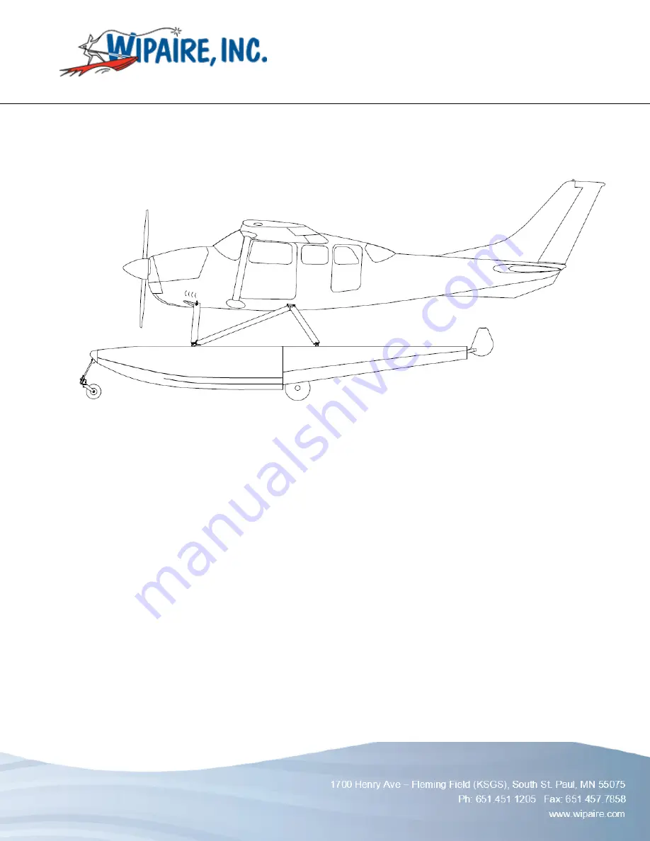
WIPLINE 3730 & 3900 FLOATS

P/N  1002551         

 Revision K  

                             Page 1                          

SERVICE MANUAL AND 

INSTRUCTIONS FOR CONTINUED AIRWORTHINESS 

FOR WIPLINE MODEL 3730/3900 

AMPHIBIOUS AND SEAPLANE FLOATS

Revision K


WIPLINE FLOATS • SKIS • MODIFICATIONS • AIRCRAFT SALES 

AVIONICS  • INTERIOR  •  MAINTENANCE •  PAINT REFINISHING 

Summary of Contents for Wipline 3730

Page 1: ...002551 Revision K Page 1 SERVICE MANUAL AND INSTRUCTIONS FOR CONTINUED AIRWORTHINESS FOR WIPLINE MODEL 3730 3900 AMPHIBIOUS AND SEAPLANE FLOATS Revision K WIPLINE FLOATS SKIS MODIFICATIONS AIRCRAFT SALES AVIONICS INTERIOR MAINTENANCE PAINT REFINISHING ...

Page 2: ...SERVICE MANUAL ICA WIPLINE 3730 3900 FLOATS Page 2 Revision K P N 1002551 THIS PAGE INTENTIONALLY LEFT BLANK ...

Page 3: ...5 11 20 21 Added Dow Corning DC4 Corrosion X and Mobil Aviation Grease SHC 100 to approved product list Modified torque limits section 12 4 2015 H 8 Added reference for Structural Repair Manual part number 1008274 in introduction 5 1 2019 J 11 13 21 23 25 Added information about corrosion limits Added note about STA Lube Added STA Lube to Brake Caliper Grease Removed inspection column from Mainten...

Page 4: ...SERVICE MANUAL ICA WIPLINE 3730 3900 FLOATS Page 4 Revision K P N 1002551 THIS PAGE INTENTIONALLY LEFT BLANK ...

Page 5: ...CHAPTER 1 GENERAL INFORMATION 9 CHAPTER 2 FLOAT HULL MAINTENANCE 11 CHAPTER 3 CORROSION 17 CHAPTER 4 HYDRAULIC SYSTEM 19 CHAPTER 5 MAIN LANDING GEAR AND RETRACTOR 23 CHAPTER 6 NOSE GEAR AND RETRACTOR 29 CHAPTER 7 ELECTRICAL SYSTEM 33 CHAPTER 8 REPAIRS AND MAINTENANCE 37 CHAPTER 9 TROUBLE SHOOTING 47 ...

Page 6: ...IGURE 2 2 JACKING LOCATION 14 FIGURE 2 3 FLOAT SECURING LOCATIONS 15 FIGURE 2 4 FLOAT SECURING LOCATIONS OVERVIEW 16 FIGURE 4 1 HYDRAULIC SYSTEM 185 21 FIGURE 4 2 HYDRAULIC SYSTEM 206 22 FIGURE 5 1 LUBRICATION CHART MAIN GEAR 3730 25 FIGURE 7 1 SCHEMATIC LANDING GEAR ELECTRICAL SYSTEM 34 FIGURE 7 2 SCHEMATIC LANDING GEAR ELECTRICAL SYSTEM 35 ...

Page 7: ...se refer to the Structural Repair Manual For Wipline Aluminum Floats part number 1008274 It is available free of charge online at www wipaire com The service products referred to throughout this manual are described by their trade name and may be purchased from Wipaire Parts Department To contact Wipaire for technical support or parts sales call or email Wipaire Inc Customer Service 1700 Henry Ave...

Page 8: ...SERVICE MANUAL ICA WIPLINE 3730 3900 FLOATS Page 8 Revision K P N 1002551 THIS PAGE INTENTIONALLY LEFT BLANK ...

Page 9: ...SERVICE MANUAL ICA WIPLINE 3730 3900 FLOATS P N 1002551 Revision K Page 9 CHAPTER 1 GENERAL INFORMATION CONTENTS 1 0 GENERAL 10 ...

Page 10: ...erated with ball bearing pulleys Water rudder cables tie into the existing aircraft rudder system The main landing gear has a 5 00 x 5 6 ply tires and the nose landing gear has a 3 50 x 10 4 ply tire The gear system is hydraulically actuated and driven by two hydraulic pumps Brakes are hydraulic and have a caliper on each main wheel Steering on land is accomplished by differential braking The nose...

Page 11: ...002551 Revision K Page 11 CHAPTER 2 FLOAT HULL MAINTENANCE CONTENTS 2 1 GENERAL 12 2 2 HARD LANDING AND DAMAGE INVESTIGATION 12 2 3 CLEANING 12 2 4 SEALING 12 2 5 TOWING 13 2 6 HOISTING 13 2 7 LEVELING 13 2 8 JACKING PROCEDURES 13 2 9 JACK REMOVAL 16 ...

Page 12: ...st trail water line marks and barnacle type deposits After saltwater operation washing with fresh water should be done daily with special attention to hard to reach places such as seams wheel wells areas underneath strut covers etc Float interior should be flushed if evidence of saltwater in compartments is noted The float interior should be flushed if salt water enters the compartments it s easy ...

Page 13: ...g attach points If the lifting rings are not installed reference applicable aircraft maintenance service manual for additional hoisting specifications Lake Air Training and Pilot Shop has this hoisting rig available for purchase Contact Wipaire Customer Service for additional guidance in removal or installation of floats CAUTION Make sure nothing is under or above the airplane or floats when hoist...

Page 14: ...t have the parts for modification It is recommended a similar modification be performed to the jack saddle to prevent the slippage of the cradle 1 Center cradle on saddle and position so cradle is as far aft on the main keel as possible without interfering with main gear as it decompresses as shown in Figure 2 2 NOTE If desired to prevent possible cosmetic damage to float use material to separate ...

Page 15: ... needed to slightly lift the float into a high enough position for the main jack 1 Secure floats with fore and aft supports as shown in Figure 2 3 and Figure 2 4 FIGURE 2 3 FLOAT SECURING LOCATIONS ALTERNATE JACKING METHOD IF WIPAIRE JACKING FIXTURE IS NOT AVAILABLE 8000A model shown for reference only ...

Page 16: ...eighted bags are still located above the nose gear 4 Position 1 person at each fore and aft of each float and 1 person at the jacking location of one float 5 Remove all fore and aft supports as shown in Figure 2 3 and Figure 2 4 6 Using modified jack saddle as shown in Figure 2 1 center jack saddle in center of cradle on 1 of the floats 7 Lift aircraft to clear fore and aft cradle stands and remov...

Page 17: ...SERVICE MANUAL ICA WIPLINE 3730 3900 FLOATS P N 1002551 Revision K Page 17 CHAPTER 3 CORROSION CONTENTS 3 0 CORROSION 18 ...

Page 18: ...sion blistering flaking and pitting may be removed by heavy sanding or grinding and applying chromic acid No more than 1 3rd the thickness of skin material should be removed before complete replacement or reinforcement of an area is necessary After removing the corroded area restore area to original finish prime and enamel BOESHIELD T9 Corrosion X or ACF 50 may also be applied to stop corrosion Re...

Page 19: ...SERVICE MANUAL ICA WIPLINE 3730 3900 FLOATS P N 1002551 Revision K Page 19 CHAPTER 4 HYDRAULIC SYSTEM CONTENTS 4 1 OPERATION 20 4 2 MAINTENANCE 20 4 3 BLEEDING THE SYSTEM 20 ...

Page 20: ...an external relief valve to protect against thermal expansion when line pressure exceeds 1900 psi The selection of gear up or gear down is accomplished by a cockpit mounted control valve Each float gear has individual indicator lights on the control valve allowing the pilot to confirm that each gear has fully retracted or extended 4 2 MAINTENANCE Maintenance of the hydraulic system is very easy ke...

Page 21: ...SERVICE MANUAL ICA WIPLINE 3730 3900 FLOATS P N 1002551 Revision K Page 21 FIGURE 4 1 HYDRAULIC SYSTEM 185 Numbers refer to Parts Manual only ...

Page 22: ...SERVICE MANUAL ICA WIPLINE 3730 3900 FLOATS Page 22 Revision K P N 1002551 FIGURE 4 2 HYDRAULIC SYSTEM 206 Numbers refer to Parts Manual only ...

Page 23: ...N 1002551 Revision K Page 23 CHAPTER 5 MAIN LANDING GEAR AND RETRACTOR CONTENTS 5 1 OPERATION 24 5 2 LUBRICATION 24 5 3 REMOVAL OF MAIN GEAR AND RETRACTOR 26 5 4 ADJUSTMENT MAIN GEAR 26 5 5 INSERTION 26 5 6 SERVICING OLEO STRUT 27 5 7 TIRE SIZE 27 ...

Page 24: ... places of grease access and type of zerk to use Use only waterproof grease recommended in Products Chart At brake installation apply STA Lube synthetic brake and caliper grease or equivalent to brake caliper pins On Lubrication Chart note 1 is a standard grease zerk One is located on lower hook where actuating cylinder is attached and one on end of each wheel axle The grease zerks on axle ends al...

Page 25: ...SERVICE MANUAL ICA WIPLINE 3730 3900 FLOATS P N 1002551 Revision K Page 25 FIGURE 5 1 LUBRICATION CHART MAIN GEAR 3730 1 STANDARD GREASE ZERK 2 NEEDLE POINT GREASE HOLE 3 APPLY GREASE THESE SURFACES ...

Page 26: ... let it snap over the bar in the drag brace and need not be adjusted to raise so high as to miss the rod completely as this can cause the pivot to hit the rod while the gear is being retracted Usually if a gear has been retracted while the aircraft was on the ground this rod will be bent because the pivot is in the wrong position pull instead of push when the drag brace comes up With this done the...

Page 27: ...in float 2 Release air pressure and extend oleo 3 Remove entire plug from top of air chamber and fill with Mil H 5606 red hydraulic oil using pump can Get air to come out as you pump in oil 4 Completely compress oleo and let excess oil run out 5 Reinstall plug and let aircraft weight down on gear 6 Inflate cylinder 1 7 8 inches of exposed piston with empty aircraft 5 6 SERVICING OLEO STRUT 1 5 00 ...

Page 28: ...SERVICE MANUAL ICA WIPLINE 3730 3900 FLOATS Page 28 Revision K P N 1002551 THIS PAGE INTENTIONALLY LEFT BLANK ...

Page 29: ...0 FLOATS P N 1002551 Revision K Page 29 CHAPTER 6 NOSE GEAR AND RETRACTOR CONTENTS 6 1 OPERATION 30 6 2 WHEEL AND CASTOR 30 6 3 LUBRICATION 30 6 4 REMOVAL 30 6 5 ADJUSTMENT 30 6 6 TIRE SIZE 31 6 7 INSERTION 31 6 8 NOSE BOX TRACK WEAR 31 ...

Page 30: ...shaft in the housing and centering the wheel during flight by means of a flat in the circumference of the groove A nylon thrust washer is located on top of the castoring pin 6 2 WHEEL AND CASTOR Needle type grease fittings are also used in the nose gear and retracting mechanism There are two needle style and two normal styles in each nose gear The needle styles are on the truck pivots and the stan...

Page 31: ... access hole on top of nose box is covered and sealed before installation 6 7 INSERTION Due the wear over time the roller slide block places on the track as the gear are retracted the block needs to be measured for the amount of wear The tolerance for wear is 050 inches If the wear is or is less than the limit it can still be used If the wear in the track is greater than 020 inches the block must ...

Page 32: ...SERVICE MANUAL ICA WIPLINE 3730 3900 FLOATS Page 32 Revision K P N 1002551 THIS PAGE INTENTIONALLY LEFT BLANK ...

Page 33: ...SERVICE MANUAL ICA WIPLINE 3730 3900 FLOATS P N 1002551 Revision K Page 33 CHAPTER 7 ELECTRICAL SYSTEM CONTENTS 7 0 ELECTRICAL SYSTEM 34 ...

Page 34: ...consists of the following components Pump motor pressure switch solenoid contractor 20 amp circuit breaker and the separate system of indicating lights and switches as per the electrical schematic of Figure 7 1 and Figure 7 2 7 0 ELECTRICAL SYSTEM FIGURE 7 1 SCHEMATIC LANDING GEAR ELECTRICAL SYSTEM ...

Page 35: ...SERVICE MANUAL ICA WIPLINE 3730 3900 FLOATS P N 1002551 Revision K Page 35 FIGURE 7 2 SCHEMATIC LANDING GEAR ELECTRICAL SYSTEM ...

Page 36: ...SERVICE MANUAL ICA WIPLINE 3730 3900 FLOATS Page 36 Revision K P N 1002551 THIS PAGE INTENTIONALLY LEFT BLANK ...

Page 37: ...OATS P N 1002551 Revision K Page 37 CHAPTER 8 REPAIRS AND MAINTENANCE CONTENTS 8 1 FLOAT HULL MAINTENANCE GENERAL 38 8 2 REPAIRING FLOAT HULL SKINS 38 8 3 REPAIRING FLOAT HULL EXTRUSIONS 38 8 4 SERVICE SCHEDULE 38 8 5 INSPECTION CHECKLIST 42 ...

Page 38: ...more frequent intervals When conducting an inspection at 25 hours all items marked for 25 hours would be accomplished When conducting an inspection at 50 hours the 25 and 50 hour items would be accomplished When conducting an inspection at 100 hours the 25 50 and 100 hour items would be accomplished When conducting an inspection at 200 hours the 25 50 100 and 200 hour items would be accomplished A...

Page 39: ...cal Insulating Compound Dow Corning 4 DC4 Dow Corning Corporation Float Sealant 890 B2 or B4 Pro Seal Company PR 1440 C PPG Aerospace 1422 B2 B4 or B6 Pro Seal Company RTV Silicones General Electric SIKAFLEX 201 or 252 Sika Manufacturing If existing grease cannot be identified you must lubri flush all float grease fittings until visibly exhausting all old grease and new grease is coming out Additi...

Page 40: ...oration Metal Parts For security of attachment cracks metal distortion broken welds corrosion condition of paint and any other apparent damage Wiring For security chafing burning defective insulation loose or broken terminals corroded terminals Bolts in Critical Area For corrosion correct torque when installed or when visual inspection indicates a need for a torque check Nut torque should be appli...

Page 41: ...ts Spray all joints with light penetrating oil such as LPS 3 to ensure lubrication at all times Electrical Connections Apply SP 400 SOFT SEAL or LPS 500 to all electrical connections to prevent corrosion Hydraulic Fluid For use in all hydraulic systems including brakes MIL H 5606 ...

Page 42: ...ondition security operation and excessive wear X Pumper Tube Installation inspect for condition security routing of hoses X Water Rudder System Water Rudder Boots inspect for cuts tears and condition X Water Rudder Steering and retract systems inspect the following cables for broken wire cable fittings for cable slippage cracks and distortion cable pulleys for freedom of rotation and cable guard p...

Page 43: ...nspect wiring mounting and general condition X Landing Gear Systems Lubricate nose gear tracks and pivot X Nose Gear Box Block Tracks measured at slide route for wear 050 inches or less wear tolerance X Nose gear pivot blocks and forks inspect for condition lubrication corrosion paint X Nose and main wheel bearing grease Zerk fittings X Hydraulic Fluid Level X Wheels and tire inspect for wear pres...

Page 44: ... condition lubrication leakage corrosion and cleanliness X Nose gear springs scotch ply springs inspect for cracks delamination and paint X Main gear drag link garlock bushings inspect for condition lubrication corrosion X Main gear oleos inspect for evidence of leakage proper extension check cylinder for corrosion pitting cleanliness and security X Hydraulic lines and fittings inspect for leaks c...

Page 45: ...traction test Inspect main gear up and down hooks for proper engagement X Inspect nose gear trolley for proper travel X Inspect nose gear for excessive side play in the down position X Perform emergency gear extension if equipped X Nose and main wheel bearings disassemble and inspect X INSPECTION TIME LIMITS HOURS MECH INITIALS 25 50 100 200 RT LT ...

Page 46: ...SERVICE MANUAL ICA WIPLINE 3730 3900 FLOATS Page 46 Revision K P N 1002551 THIS PAGE INTENTIONALLY LEFT BLANK ...

Page 47: ...SERVICE MANUAL ICA WIPLINE 3730 3900 FLOATS P N 1002551 Revision K Page 47 CHAPTER 9 TROUBLE SHOOTING CONTENTS 9 0 TROUBLE SHOOTING 48 ...

Page 48: ... and it is verified that voltage was actually applied to the motor it can be assumed that the motor is bad 2 PROBLEM Powerpack does not shut off after gear reaches position Probable cause a Faulty pressure switch b Faulty or dirty pressure relief valve allowing insufficient pressure buildup Remedy a Replace pressure switch b Clean and check relief valve 3 PROBLEM Powerpack shuts off before gear re...

Page 49: ...ing gear cycle Probable cause a Binding retraction unit b Pressure switch cut off limit too low Remedy a Investigate for free operation gear that retracts last b Replace pressure switch 6 PROBLEM Slow gear operation cycle considerably longer than 23 seconds Probable cause a Plugged oil screen b Poor electrical connection to motor c Poor motor d Worn pump gears Remedy a Clean intake screen located ...

Reviews: