background image


User Manual                                                                                  Marine Bridge Panel PC System 


Marine Panel Computer 


USER MANUAL


Version: 1.1 


R15IV3S-MRXX 

15.0 inch Marine Bridge Panel PC System


R17IV3S-MRM1 

17.0 inch Marine Bridge Panel PC System 

R19IV3S-MRXX 

19.0 inch Marine Bridge Panel PC System


W24L100-MRA1IV3S 

24.0 inch Marine Bridge Panel PC System 


Summary of Contents for R15IV3S-MR series

Page 1: ...el Computer USER MANUAL Version 1 1 R15IV3S MRXX 15 0 inch Marine Bridge Panel PC System R17IV3S MRM1 17 0 inch Marine Bridge Panel PC System R19IV3S MRXX 19 0 inch Marine Bridge Panel PC System W24L1...

Page 2: ...Bridge Panel PC System REVISION HISTORY REVISION AUTHOR DATE DESCRIPTION 1 00 Marc Tsai June 4 2013 First version release 1 10 Jonathan Chi Nov 29 2018 Added 17 and 24 Marine Panel PC models Copyrigh...

Page 3: ...Do not allow anything to rest on the power cord Do not locate this product where persons will walk on the cord Never push objects of any kind into this product through cabinet slots as they may touch...

Page 4: ...lity 4 x M6x30 black screw bolt with M6 nut Notice Only be used to screw the display into a console If you prefer your own bolts please make sure to use M6 and 30mm in length 10 4 inch above display u...

Page 5: ...escription Note 1 x CD for Recovery CD for Operation System Windows 7 Optional with Windows 7 pre installed 1 x Windows 7 Recovery Users Guide Optional with Windows 7 pre installed 1 x Standard Power...

Page 6: ...e Wire Resistive Touch screen Optional 1 10 1 3 2 Secure Touch Surface Wave Touch screen Optional 2 11 CHAPTER 2 INSTALLATION 13 2 1 GENERAL INSTALLATION 13 2 2 INSTALLATION NOTICE 16 2 2 1 Brightness...

Page 7: ...User Manual Marine Bridge Panel PC System 6 CHAPTER 1 General Information...

Page 8: ...mming technology that can control backlight brightness linearly from nearly 0 to 100 by a dimming knob In the night vision it s very suitable for marine applications High Brightness Optional Our extra...

Page 9: ...our Panel PC solution enhanced shock and vibration resistance Customize your marine products Base on our well experience module competence we can do very flexible and tailor made design fulfilling an...

Page 10: ...Manual Marine Bridge Panel PC System 9 1 2 Basic Construction of Marine Panel PC The state of the art modulized technology can integrate all marine display components flexibly Figure 1 1 Basic Constru...

Page 11: ...ts The flexible coversheet acts only as a voltage measuring probe This means the touchscreen will continue working properly even with non uniformity in the cover sheet s conductive coating The result...

Page 12: ...the receiving transducer which reconverts them into an electrical signal a digital map of the touchscreen surface When you touch the screen you absorb a portion of the wave traveling across it The re...

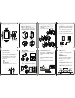
Page 13: ...User Manual Marine Bridge Panel PC System 12 CHAPTER 2 Installation...

Page 14: ...lation methods Including panel flush mounting bracket mounting ceiling wall mounting etc For panel flush mounting is normally for a ship s wheelhouse use it s easy to follow few steps to fix the displ...

Page 15: ...ne product on the fixture console from the front and screw by four M6 x 30 mm black bolts with nuts Step2 Use M4x 15mm bolts to drill through the fixture into the mounting holes on the rear side of IP...

Page 16: ...User Manual Marine Bridge Panel PC System 15 Step3 Check the finished mounting concept Please Note VESA and wall mount with mounting kit by special request...

Page 17: ...lease make sure the right way to protect the knob 2 2 2 Cable Connection Precaution Make sure to use qualified shielded signal cable to connect to Marine products These cables including RS232 VGA HDMI...

Page 18: ...User Manual Marine Bridge Panel PC System 17 2 2 3 Isolation RS422 485 Jumper Settings 1 RS 485 RS 422 2 RS 232 RS2T4 420 RS2T4 420...

Page 19: ...ctor DB9 Female Related connector DB9 Male Pin No Symbol Description 1 P1 DCD D TX RX 2 P2 RXD D TX RX 3 P3 TXD RX TX 4 P4 DTR RX TX 5 GND Ground 6 P6 DSR NC 7 P7 RTS NC 8 P8 CTS NC 9 P9 RI NC Pins de...

Page 20: ...User Manual Marine Bridge Panel PC System 19 4 P4 RX 3 RS 422 Slave Pin No Symbol Description 1 P1 RX 2 P2 RX 3 P3 TX 4 P4 TX...

Page 21: ...User Manual Marine Bridge Panel PC System 20 CHAPTER 3 Operating the Panel PC...

Page 22: ...inal AC Std 90V to 265V power input is also available for AC version option use standard power cord to connect to the AC power inlet RS232 serial port for connection COM1 COM2 COM3 COM4 The Marine Pan...

Page 23: ...and Storage status LED indicator also very clear for user to control the system situation Figure 3 2 In Front User Controls for 10 4 inch to 17inch The Dimming Knob The TFT LCD display support hyper...

Page 24: ...User Manual Marine Bridge Panel PC System 23 Appendix...

Page 25: ...hly prone to scratching Do not use ketene type material ex Acetone Ethyl alcohol toluene ethyl acid or Methyl chloride to clear the panel It may permanently damage the panel and void the warranty 5 If...

Page 26: ...ght is the brighter the LCD will appear As a result the modified LCD is viewable under lighting conditions including direct sunlight The following table shows the outdoor readability for the Marine Br...

Reviews: