Wiltron 680XXB, Operation Manual
The Wiltron 680XXB Operation Manual is a comprehensive guide for users of this advanced electronic testing equipment. This manual can be downloaded for free from our website, providing detailed instructions on how to operate and maintain your Wiltron 680XXB. Get your copy today at manualshive.com.
Share
Download


Reviews:
No comments
Related manuals for 680XXB
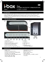
Trax
Brand: i-box Pages: 4

Explorer 1500
Brand: Jackery Pages: 20

R4400
Brand: Rainier Pages: 27

SOLAR e POWER CASE 800
Brand: Wagan Pages: 19

APGG7500
Brand: All-Power Pages: 14

FG085 Function Generator
Brand: JYE Tech Pages: 2

M9383A PXIe
Brand: Keysight Technologies Pages: 36

APG3002
Brand: ALL POWER AMERICA Pages: 32

SRD 220
Brand: Sencor Pages: 12

PG6580ECO
Brand: Pulsar Pages: 26

PG15KVTW
Brand: Pulsar Pages: 26

SH2900DX
Brand: Yamakoyo Pages: 27

SPEAKER RETRO
Brand: Create Pages: 24

005308-0
Brand: Generac Power Systems Pages: 48

004991-0
Brand: Generac Power Systems Pages: 48

030208-1
Brand: Briggs & Stratton Pages: 6

01655-3
Brand: Briggs & Stratton Pages: 28

100402
Brand: Champion Global Power Equipment Pages: 33


