Wheatstone IP-12, Technical Manual
Get the comprehensive technical manual for the Wheatstone IP-12, a high-quality audio console. Easily download the user manual for free from our website and gain access to detailed instructions on how to make the most out of your product. manualshive.com.
Share
Download


Reviews:
No comments
Related manuals for IP-12

BO100
Brand: Behringer Pages: 2

Architectural Acoustics MMA 800T
Brand: Peavey Pages: 12

Dookie Drive DD25V3
Brand: mxr Pages: 5

18mcfm5qlb
Brand: Master Chef Pages: 7

GIG-6
Brand: DAPAudio Pages: 19

EXODUS ATOM MXR 1208A
Brand: Gecko Pages: 23

VIENNA CHORUS
Brand: Radial Engineering Pages: 2

Dito Ditomix 5
Brand: Electrolux Pages: 12

Dito XBEF20AST
Brand: Electrolux Pages: 4

Dito 603388
Brand: Electrolux Pages: 2

Dito Ditomix 5
Brand: Electrolux Pages: 76

Dito 603389
Brand: Electrolux Pages: 2

DX-50BT
Brand: Pronomic Pages: 6

Prodigy
Brand: Fairlight Pages: 148

KAHTNSNDMIX
Brand: Kogan Pages: 8
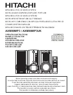
AXM89MP3
Brand: Hitachi Pages: 16

DCM1075
Brand: Philips Pages: 21

DCD322/12
Brand: Philips Pages: 39


