


O
PERATION
& S
ERVICE
M
ANUAL
65-11-7
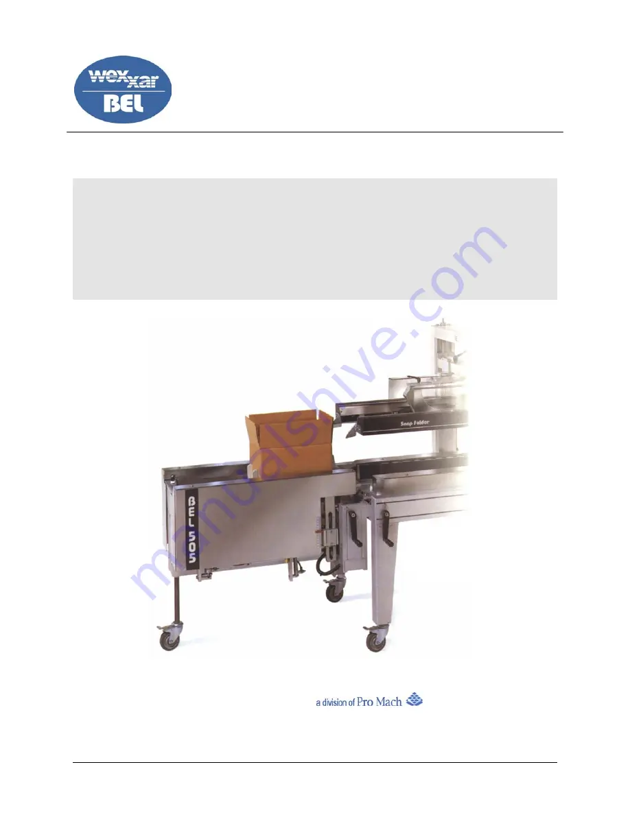
BEL 505 / BEL 505S
S
EMI
-A
UTOMATIC
C
ASE
F
ORMER
AND
P
ACKING
S
TATION
Wexxar Packaging Inc
.
E-mail: [email protected]
Phone (604) 270-0811 • Fax (604) 270-7897
65-11-07 2/5/2007
The Wexxar BEL 505's Operation & Service Manual is a comprehensive guide available for free download on our website. This manual offers detailed instructions and important information about operating the BEL 505, ensuring optimal performance and longevity. Get your free manual now at manualshive.com.
O
PERATION
& S
ERVICE
M
ANUAL
65-11-7
BEL 505 / BEL 505S
S
EMI
-A
UTOMATIC
C
ASE
F
ORMER
AND
P
ACKING
S
TATION
Wexxar Packaging Inc
.
E-mail: [email protected]
Phone (604) 270-0811 • Fax (604) 270-7897
65-11-07 2/5/2007


