Weishaupt WL10/3-D Z, Installation And Operating Instruction
The Weishaupt WL10/3-D Z Installation and Operating Instruction Manual is available for free download on our website. This comprehensive manual provides step-by-step instructions for the installation and operation of the Weishaupt WL10/3-D Z product. Get all the information you need to set up and use your Weishaupt WL10/3-D Z from manualshive.com.
Share
Download


Reviews:
No comments
Related manuals for WL10/3-D Z

TBL 210P
Brand: baltur Pages: 80

MAIOR P 15
Brand: Ecoflam Pages: 28

DCS PBE1
Brand: Fisher & Paykel Pages: 16

ZT0
Brand: Hegwein Pages: 53

TBG 85P
Brand: baltur Pages: 64

TBG 35P
Brand: baltur Pages: 72

TBG 120P
Brand: baltur Pages: 74

TBG 110 LX ME /V
Brand: baltur Pages: 92

GI 350 ME
Brand: baltur Pages: 90

TBG 120ME
Brand: baltur Pages: 106

AF
Brand: R.W. BECKETT Pages: 2
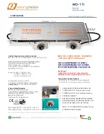
MO-111
Brand: QookingTable Pages: 5

96898
Brand: Campingaz Pages: 28

W2001
Brand: PT Pages: 8

BTL 4P
Brand: baltur Pages: 60

SmartBurner
Brand: PTC Pages: 37

085-3259-6
Brand: Master Chef Pages: 18

Art-SB1
Brand: artisan Pages: 14


