


www.wavetronix.com
801.734.7200
QUICK START GUIDE
Click 304 USB to Serial
2
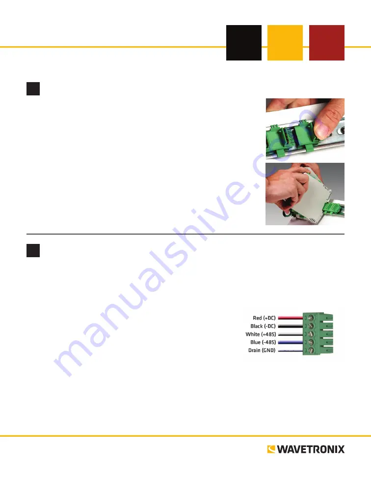
Wire power and communication
If you are using a Click 200 surge protector, power and communication are provided to the device through
the T-bus (see the Click 200 Quick-reference Guide). If you don’t have a Click 200 surge protector, use the
following steps to wire power and communication into the device:
1
Plug a T-bus 5-screw terminal block into the first T-bus connector.
2
Wire DC power (10–30 V) from the power supply into the first
screw terminal on the 5-screw terminal block; wire -DC into the
second screw terminal.
3
C485, -485 and GND to either the remaining three
screw terminals on the 5-screw terminal block or to the screw
terminals in the pluggable screw terminal block on the top of the
device (see labels for correct wiring).
The Click 304 has a few other communication ports.
˽
DB-9 connector –
Connect a straight-through cable for RS-232 communication
˽
RJ-11 jack –
Connect a jumper cable for RS-485 communication
1
Mount the device
Each device mounts over a T-bus for power and communication:
1
If the device was shipped with the T-bus connector attached, remove the
connector from the module.
2
Snap the connector onto the DIN rail by positioning it over the rail with
the male connector pointing to the right. Hook one arm over the edge of
the DIN rail and press down on the other arm until it snaps into place.
3
Connect the T-bus connector to the rest of the T-bus by sliding them
together until you hear them snap into place.
4
Mount the device onto the DIN rail: position it properly over the T-bus
connector, hook the lip over the lower edge of the DIN rail, and use a
rocking motion to snap the module into place.


