background image

September 16, 2019
©  S&C Electric Company 2018-2019, all rights reserved

Instruction Sheet  461-509

TripSaver

®

 II Cutout-Mounted Recloser

Outdoor Distribution (15.5 kV and 25 kV)

TripSaver

®

 II Communications via Gateway

Installation, Operation, and Configuration

Table of Contents

Section Page

Section Page

Introduction

Qualified Persons   .  .  .  .  .  .  .  .  .  .  .  .  .  .  .  .  .  .  .  .  .  .  .  .  .  .  . 2
Read this Instruction Sheet    .  .  .  .  .  .  .  .  .  .  .  .  .  .  .  .  .  .  . 2
Retain this Instruction Sheet .  .  .  .  .  .  .  .  .  .  .  .  .  .  .  .  .  .  .  2
Proper Application    .  .  .  .  .  .  .  .  .  .  .  .  .  .  .  .  .  .  .  .  .  .  .  .  .  . 2
Warranty   .  .  .  .  .  .  .  .  .  .  .  .  .  .  .  .  .  .  .  .  .  .  .  .  .  .  .  .  .  .  .  .  .  . 2

Safety Information

Understanding Safety-Alert Messages  .  .  .  .  .  .  .  .  .  .  . 3
Following Safety Instructions   .  .  .  .  .  .  .  .  .  .  .  .  .  .  .  .  .  . 3
Replacement Instructions and Labels    .  .  .  .  .  .  .  .  .  .  . 3

Safety Precautions

   .  .  .  .  .  .  .  .  .  .  .  .  .  .  .  .  .  .  .  .  .  .  .  .  .  4

Shipping and Handling

Packing   .  .  .  .  .  .  .  .  .  .  .  .  .  .  .  .  .  .  .  .  .  .  .  .  .  .  .  .  .  .  .  .  .  .  . 5
Inspection   .  .  .  .  .  .  .  .  .  .  .  .  .  .  .  .  .  .  .  .  .  .  .  .  .  .  .  .  .  .  .  .  . 5
Handling   .  .  .  .  .  .  .  .  .  .  .  .  .  .  .  .  .  .  .  .  .  .  .  .  .  .  .  .  .  .  .  .  .  . 5
Storage   .  .  .  .  .  .  .  .  .  .  .  .  .  .  .  .  .  .  .  .  .  .  .  .  .  .  .  .  .  .  .  .  .  .  . 5
Returning    .  .  .  .  .  .  .  .  .  .  .  .  .  .  .  .  .  .  .  .  .  .  .  .  .  .  .  .  .  .  .  .  . 5

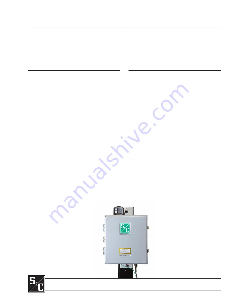
Mounting, Powering Up, and Securing the 

Communication Gateway

   .  .  .  .  .  .  .  .  .  .  .  .  .  .  .  .  .  .  .  . 6

Mounting the Communication Gateway to a Pole    .  . 7
Powering Up the Communication Gateway   .  .  .  .  .  .  . 8
Securing the Communication Gateway    .  .  .  .  .  .  .  .  .  . 8

Installing and Replacing a Radio

Installing a New Radio    .  .  .  .  .  .  .  .  .  .  .  .  .  .  .  .  .  .  .  .  .  .  . 9
Replacing a Radio    .  .  .  .  .  .  .  .  .  .  .  .  .  .  .  .  .  .  .  .  .  .  .  .  .  .10

Installing and Replacing a Backup Battery

Installing a New Battery   .  .  .  .  .  .  .  .  .  .  .  .  .  .  .  .  .  .  .  .  .  .11
Replacing a Battery    .  .  .  .  .  .  .  .  .  .  .  .  .  .  .  .  .  .  .  .  .  .  .  .  .12

Installing Remote Antenna Kits

Installing Remote Antenna 
  Kit 903-002702-02/01    .  .  .  .  .  .  .  .  .  .  .  .  .  .  .  .  .  .  .  .  .13
Installing Remote Antenna 
  Kit 903-002701-01/02    .  .  .  .  .  .  .  .  .  .  .  .  .  .  .  .  .  .  .  .  .14
Installing Remote Antenna 
  Kit 903-002700-02/03   .  .  .  .  .  .  .  .  .  .  .  .  .  .  .  .  .  .  .  .  .14

Installing and Replacing a Local Antenna

Installing Local Antenna 904-002450-02     .  .  .  .  .  .  .  .15
Replacing a Local Antenna    .  .  .  .  .  .  .  .  .  .  .  .  .  .  .  .  .  .  .15

Configuring the Communication Gateway

Software User’s Guide   .  .  .  .  .  .  .  .  .  .  .  .  .  .  .  .  .  .  .  .  .  .  .16
General Status   .  .  .  .  .  .  .  .  .  .  .  .  .  .  .  .  .  .  .  .  .  .  .  .  .  .  .  .  .18
Gateway Settings   .  .  .  .  .  .  .  .  .  .  .  .  .  .  .  .  .  .  .  .  .  .  .  .  .  .  .19
TripSaver II Device Management   .  .  .  .  .  .  .  .  .  .  .  .  .  .  35
TripSaver II Gang Operation  .  .  .  .  .  .  .  .  .  .  .  .  .  .  .  .  .  .  39
TripSaver II Service Center
  Configuration Software    .  .  .  .  .  .  .  .  .  .  .  .  .  .  .  .  .  .  .  43
DNP3 Master Settings    .  .  .  .  .  .  .  .  .  .  .  .  .  .  .  .  .  .  .  .  .  .  46
DNP3 Outstation Settings .  .  .  .  .  .  .  .  .  .  .  .  .  .  .  .  .  .  .  .  49
User Roles    .  .  .  .  .  .  .  .  .  .  .  .  .  .  .  .  .  .  .  .  .  .  .  .  .  .  .  .  .  .  .  61
Security Settings .  .  .  .  .  .  .  .  .  .  .  .  .  .  .  .  .  .  .  .  .  .  .  .  .  .  .  63
Profile   .  .  .  .  .  .  .  .  .  .  .  .  .  .  .  .  .  .  .  .  .  .  .  .  .  .  .  .  .  .  .  .  .  .  .  71
Diagnostics   .  .  .  .  .  .  .  .  .  .  .  .  .  .  .  .  .  .  .  .  .  .  .  .  .  .  .  .  .  .  .  72
Enabling the Remote Web User Interface (UI)   .  .  .  .  74

Quick Installation Checklist

   .  .  .  .  .  .  .  .  .  .  .  .  .  .  .  .  76

Summary of Contents for TripSaver II

Page 1: ...7 Powering Up the Communication Gateway 8 Securing the Communication Gateway 8 Installing and Replacing a Radio Installing a New Radio 9 Replacing a Radio 10 Installing and Replacing a Backup Battery...

Page 2: ...Gateway system is used Retain this instruction sheet in a location where you can easily retrieve and refer to it Proper Application WARNING The equipment in this publication is only intended for a sp...

Page 3: ...ions are not followed NOTICE NOTICE identifies important procedures or requirements that can result in product or property damage if instructions are not followed Following Safety Instructions If you...

Page 4: ...em must be restricted only to qualified persons See the Qualified Persons section on page 2 2 SAFETY PROCEDURES Always follow safe operating procedures and rules 3 PERSONAL PROTECTIVE EQUIPMENT Always...

Page 5: ...t 2 Ask for a carrier inspection 3 File a claim with the carrier Also notify S C Electric Company in all instances of loss and or damage NOTICE DO NOT drop the communication gateway or subject any of...

Page 6: ...t 461 509 Mounting Powering Up and Securing the Communication Gateway Figure 1 The TripSaver II Communications Gateway Gateway Controller Module Battery Module I O PSIO Board Antenna Radio Ground wire...

Page 7: ...the communication gateway to the utility pole The gateway should be mounted no further than 100 feet 30 5 m below TripSaver II Cutout Mounted Reclosers in a clear and unobstructed line of sight Typica...

Page 8: ...e power connection terminal make the connection and tighten the ring See Figure 2 on page 7 STEP 5 After a short delay LEDs on the power supply control I O PSIO board and the gateway controller should...

Page 9: ...c linefuselocatedatthelowerrightcornerofthegateway box STEP 2 Install the radio on the mounting plate using user furnished hardware STEP 3 The wiring harness on most radios includes a power plug and d...

Page 10: ...the ac line fuse located at the lower right corner of the gateway box Reconnect the ac cable connector Follow these steps to replace a radio in the communication gateway STEP 1 Disconnect the ac powe...

Page 11: ...x STEP 2 Install the battery The battery kit includes a battery a top bracket and hardware a The battery should be installed in the lower middle section of the gateway b Install the battery using the...

Page 12: ...ected to the bottom of the gateway See Figure 2 on page 7 and then disconnect the ac line fuse located at the lower right corner of the gateway box See Figure 5 on page 11 STEP 2 Remove the pre instal...

Page 13: ...ntennas STEP 3 Slip the supplied cold shrink tube over the antenna cable and connect the end where the shrink tube was applied to the antenna Tighten finger tight STEP 4 Wrap the cable connector insid...

Page 14: ...and connect thecabletothesurgesuppressoratthebottomofcommunicationgatewaybox Waterproof this connector to industry standards The 902 to 928 MHz 3 dBi antenna includes an omnidirectional fiberglass an...

Page 15: ...EP 2 Screw in the antenna to the N type female connector STEP 3 Waterproof the connector to industry standards STEP 1 Visually inspect the antenna for damage bent not vertical STEP 2 If it needs to be...

Page 16: ...a network connection to the communication gateway See Figure 4 on page 9 Alternately a static IP address within the 192 168 1 x network may be used See Figure 9 Note To remove Windows routing conflic...

Page 17: ...s the Return key Browser versions supported include Google Chrome and Internet Explorer The Login screen will open with a username and password challenge See Figure 11 Note The default username and pa...

Page 18: ...read only activities Also if two users are sharing a single username and the users attempt to log in at the same time the older session will be silently logged out The purpose of the General Status sc...

Page 19: ...Name The Gateway Name panel allows unique naming of the communications gateway The data from this field will be delivered to the SCADA master via a DNP3 Group 0 read Enter a user defined name for the...

Page 20: ...require identification are the Static IP Address NetMask and DHCP Server Note The DHCP toggle button either enables or disables dynamic host control proto col DHCP services on physical Ethernet Port...

Page 21: ...lds with DHCP set in the On position Ethernet 2 WAN This panel defines the IP addressing for the communication gateway s Ethernet Port 2 and subsequent network linkage and settings respective to the c...

Page 22: ...address of the network device up stream of the communication gateway and determines the destination of DNP3 traffic sent to the SCADA masters s DHCP State On No fields require identification A DHCP r...

Page 23: ...user to configure settings in one communication gateway device export those settings into an XML file and then import the same settings into another communication gateway The selection of Import Conf...

Page 24: ...s a simple name value pair for example ConfigDB configuration item value 50 name gatewayAddress configuration ConfigDB where name gatewayAddress represents the communication gateway s own DNP3 address...

Page 25: ...bleObjectFlagCommLost This setting disables the COMM_LOST flag in DNP3 standard Object Flags When set to true the gateway disables the COMM_LOST flag so it will always be set to 0 When set to false th...

Page 26: ...input setpoint mappings for example DNP3 BinaryInputSetPoints binaryinputsetpoint statuspoint 0 codedescription 1 eventclass 2 binaryinputsetpoint statuspoint 3 codedescription 2 eventclass 1 BinaryIn...

Page 27: ...s screen A value of 0 corresponds to NO EVENT Integer 0 1 2 3 fixeddeadband See Fixed Deadband on the DNP3 Outstation Settings screen Set to disabled to disable fixed deadband reporting for this setpo...

Page 28: ...ort Configuration button A Web User Interface WUI dialogue box opens STEP 2 ClickontheChoose Filebutton whichinvokesaWindowsfilenavigationbox STEP 3 Navigate to the file STEP 4 Highlight the file and...

Page 29: ...utton A WUI dialogue box opens with a suggested filename for the exported configuration The default name is textFile but can be changed STEP 2 Click on the Export button STEP 3 Wait a few seconds for...

Page 30: ...ade STEP 1 Download the firmware file Firmware files can be found in the S C Customer Portal at sandc com en support sc customer portal STEP 2 Click on the Upload Firmware File button on the Firmware...

Page 31: ...cation gateway After the upload completes the gateway will confirm the upload was successful See Figure 25 as well as Figure 26 Figure 25 The Firmware Upload progress bar Figure 26 Dialog box showing...

Page 32: ...gnedbyS CElectricCompany See Figure 27 Figure 27 The firmware verification process STEP 6 After the file is verified a notification will appear Click on the OK button to dismiss this window The Upgrad...

Page 33: ...pgrade it will display a notification See Figure 31 on page 34 When the user clicks on the OK button on this notification the browser will display a screen indicating the gateway is unavailable while...

Page 34: ...ars for confirmation of the Reboot command After the user clicks on the OK button the user interface will show a Gateway Unavailable screen The entire reboot process requires approximately 5 minutes b...

Page 35: ...Saver II recloser with the USB transceiver and power module To add a TripSaver II recloser a user clicks on the Add TripSaver II Cutout Mounted Recloser button on the top right of the page A pop up di...

Page 36: ...ated with the communication gateway In addition to the serial number and TripSaver II recloser name the recloser s Transceiver ID link status and RSSI are displayed A TripSaver II recloser may be chan...

Page 37: ...oser configuration kit S C Catalog Number 5950 If using the corded power module the TripSaver II recloser must first be removed from the utility pole DANGER The TripSaver II Cutout Mounted Recloser MU...

Page 38: ...ps the pairing process will begin It is strongly recommended that the TripSaver II recloser not be paired with a gateway until both are installed in the permanent location This pairing process require...

Page 39: ...n Step 1 and Steps 2 through 7 in all TripSaver II reclosers rather than one at a time See pages 37 and 38 Contact S C with any questions The purpose of the TripSaver II Gang Operation screen is to co...

Page 40: ...e Enable Gang Operation toggle button See Figure 36 Figure 36 The Enable Gang Operation toggle button The Gang Operation Retry Time field configures the time between drop out com mands given to the re...

Page 41: ...xpected orientation change such as when the TripSaver II recloser is manually pulled out of its mounting These settings can be updated for each TripSaver II recloser by clicking on the Permanent Fault...

Page 42: ...equest When this button is clicked the user will be asked to provide a walkaway time interval in seconds After this time interval the gateway will perform the gang trip The Cancel Gang Trip Retries bu...

Page 43: ...le connected to the communication gateway s Ethernet Port 1 Refer to Instruction Sheet 461 504 for more on the operation of the service center configuration software Note The service center configurat...

Page 44: ...t 461 509 When the Service Center Configuration mode is enabled the dialogue box opens See Figure 41 Figure 41 The dialog box showing successful service center configuration activation Configuring the...

Page 45: ...E When using a communications gateway to connect to a TripSaver II recloser via the service center configuration software any configuration changes made to the communications gateway during the servic...

Page 46: ...server General DNP3 Master Settings The backhaul communications protocol is first identified by the selection of TCP UDP or Serial options in the drop down box When chosen the Save button must be clic...

Page 47: ...ts Parity and Flow Control The Baud Rate field is chosen by selecting one of the values from the drop down menu The Stop Bits Parity and Flow Control fields are radio buttons that require selection Da...

Page 48: ...Unsolicited Response field may be changed via the ON OFF toggle button The port value is used as the gateway s local listen port when either TCP or UDP transport is selected Finally the IP address fi...

Page 49: ...ications gateway will deliver information for each TripSaver II recloser mapped to separate point codes providing more efficient SCADA integrity poll messaging overhead and conserving DNP address spac...

Page 50: ...he TCP Keepalive Timer and the DNP3 Inactivity Timer fields and the Disable DNP3 Object Flag Comm_Lost toggle button specific to settings for communications between the communications gateway and the...

Page 51: ...SCADA master before performing recovery actions to restore DNP3 connectivity A value of zero 0 disables the DNP3 recovery mechanism Disable DNP3 Object Flag Comm_Lost This setting disables the Comm_Lo...

Page 52: ...ponse Subsequent retries will be sent after increasing amounts of delay to minimize network congestion in case of an extended SCADA master outage Unsolicited Transmit Delay Event Count This is the max...

Page 53: ...ges for each category Analog Inputs Counters and Binary Outputs is identical In the next section there will be a detailed overview of how to set a Status Binary Input point Screen captures will not be...

Page 54: ...y DNP Points List and Implementation Code descriptions are defined by selecting the Code Description field in line with the respective Status Point field A drop down dialogue box will open with code d...

Page 55: ...ollow these steps to input the settings STEP 1 Navigate to the field on the Status Point line STEP 2 Initiate the drop down menu by selecting the field STEP 3 Highlight the desired identifier STEP 4 S...

Page 56: ...put Points Configuration This window contains configuration parameters for analog input points Mapping these points will make them available in SCADA The field is initiated by clicking on the Analog I...

Page 57: ...alog input requirements of the SCADA system The original raw analog input data will be multiplied by the specified scaling factor prior to delivery to the SCADA master If the Fixed Deadband option is...

Page 58: ...y Counter Points Configuration This field contains configuration parameters for Counter points Mapping these points will make them available in SCADA The field is initiated by clicking on the Counter...

Page 59: ...ss 2 or Class 3 or chose the No Event option to turn off event data reporting for this field Pct Percent Deadband This field creates a range based on a percentage of the last reported value for this c...

Page 60: ...Point This is the point number the SCADA system will use when operating the command point Code Description Binary outputs are used by the SCADA master to update settings in the communication gateway...

Page 61: ...empty Finally click on the Save button Follow these steps to complete the process STEP 1 Navigate to the field on the status point line STEP 2 Initiate respective drop down boxes by selecting the fiel...

Page 62: ...ecloser status Allowed Allowed Allowed Blocked TripSaver II Gang Operation Configure gang operation settings Allowed Allowed Blocked Blocked Perform Gang Trip Cancel Gang Trip buttons Allowed Blocked...

Page 63: ...bility to tunnel all communication network traffic from the communication gateway to a customer supplied peer See Figure 56 Enabling a secure tunnel from the communications gateway creates an authenti...

Page 64: ...of how to create these secure tunnels See Figure 57 Figure 57 The Add Secure Tunnel drop down menu Clicking on the Add Secure Tunnel button initiates a menu of L2TP Ethernet IPSEC L2TP PPP IPSEC or Op...

Page 65: ...ackets from the local Ethernet interface on the communication gateway to the remote server The L2TP Ethernet packets are encapsulated within an IPSec Security Association to provide authentication enc...

Page 66: ...ber into the L2TP Peer Port box STEP 7 Enter the planned Local Tunnel ID number into the L2TP Local Tunnel ID box STEP 8 Enter the planned Tunnel Peer ID number into the L2TP Peer Tunnel ID box STEP 9...

Page 67: ...ure tunnel that encapsulates IP packets from the local interface first within PPP and subsequently within an IPSec Security Association with the remote server The L2TP PPP IPSec tunnel provides authen...

Page 68: ...erver port number in the L2TP LNS Port box STEP 6 Enter the Local private IP address into the L2TP Local IP box STEP 7 Enter the Local Network Server Subnet Mask into the L2TP LNS Subnet Mask box STEP...

Page 69: ...tunnel allows the administrator to create an OpenVPN tunnel to encapsulate IP packets from the local interface to the remote OpenVPN server Like the tunnel configuration above select the Open VPN opti...

Page 70: ...vice certificate into the Device Certificate box STEP 10 Enter the device private key into the Device Private Key box STEP 11 Click on the Add button to complete tunnel addition The configured OpenVPN...

Page 71: ...t of instructions is documented in the Enabling the Remote User Interface UI section on pages 74 and 75 Figure 62 The Remote Web Access toggle button NOTICE If an S C SpeedNet Radio is being used for...

Page 72: ...nication gateway to change his or her password credentials See Figure 63 Figure 63 The Profile screen The Diagnostics screen initiates the retrieval of the Diagnostic and Event Log files See Figure 64...

Page 73: ...terval See Figure 65 Figure 65 The Diagnostic Log retrieval interval dialogue box If the Download button is clicked a notification of file download completion appears and the Log file will be saved in...

Page 74: ...emote Web Access slide selector STEP 3 In the DNP3 Outstation Settings Command Binary Output a binary output status point must be configured with code description 1 Communication Gateway remote web us...

Page 75: ...DNP3 Master Scada Master send the following command to the status point configured in Command Binary Output step Direct Relay control command a Type Latching Relay b Value Latch On To Enable STEP 7 C...

Page 76: ...alled and connected The communication gateway is mounted securely on the pole The communication gateway is grounded The ac power cable is connected and control power is available The remote antenna if...

Reviews: