background image

1 of 15

WX-501-0518 • 01.22

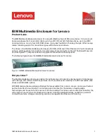
Using the Click 112/114

The Click 112 and 114 are 2-channel and 4-channel contact closure cards that can be used with the SmartSensor 

Matrix, Advance, or HD. These cards plug into any standard detector rack card slot and can be connected to the 

sensor via a surge protector like the Click 222.

Physical Features

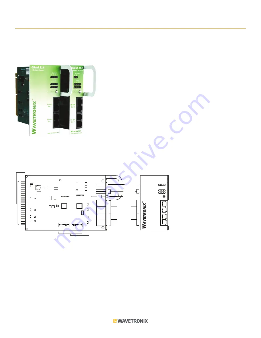
The following sections describe the physical features of the Click 112/114.

Mode Switch

LED


Indicators

Channel 

Indicators

RS-485 

Connectors

Bus 2

RS-485


Connectors

Bus 1

Rack Connector


DIP Switches

Click 114

4 Contact Closures

www.wavetronix.com

PWR PU TD RD

1 2 3 4

Menu

1 2 3 4

Channel

Mode Switch

RS-485

Bus 1

RS-485

Bus 2

On

Off

On

Off

TOP

FRONT

Communication Ports

The Click 112/114 contain two independent serial communications ports. Each port is made up of two RJ-11 

connectors, which make it simple to daisy-chain multiple cards together and create an RS-485 bus. The two 

RJ-11 RS-485 data buses can be connected to a SmartSensor through a surge protection module (the cards are 

designed for use with the Click 222, though the Click 200 can be used as well), or through a serial data converter. 

Bus 1 should be used to report vehicle data, and bus 2 should be used for configuration. Having one bus 

dedicated to each function leads to optimum Click 112/114 performance. On certain newer devices, the buses are 

labeled as Data and Control to let you know which one to use.

0518

Summary of Contents for Click 112

Page 1: ...nu 1 2 3 4 Channel Mode Switch RS 485 Bus 1 RS 485 Bus 2 On Off On Off TOP FRONT Communication Ports The Click 112 114 contain two independent serial communications ports Each port is made up of two RJ 11 connectors which make it simple to daisy chain multiple cards together and create an RS 485 bus The two RJ 11 RS 485 data buses can be connected to a SmartSensor through a surge protection module...

Page 2: ...urposes The menu indicator LEDs include two rows of LEDs see the figure above The lower row contains Level 1 indicators while the upper row contains Level 2 indicators Each level consists of four LEDs numbered 1 4 left to right Level 1 LEDs the multicolored row display which menu item is active These Level 1 LEDs are dual purpose each indicating both menu selection as well as a normal operation st...

Page 3: ... 15 No connection S Channel 3 output 16 Channel 3 status output T Channel 3 output 17 No connection U No connection 18 No connection V No connection 19 No connection W Channel 2 output 20 Channel 2 status output X Channel 2 output 21 No connection Y Channel 4 output 22 Channel 4 status output Z Channel 4 output Channels 3 and 4 exist only in the Click 114 In the Click 112 any pin marked here as be...

Page 4: ...es section of this document Note Any setting which has been configured via the DIP switches will be read only in Click Supervisor and the front panel menu One benefit of using DIP switches to configure is that if you ever have a field service call and need to replace a Click 112 114 all you need to do is match the pattern of the DIP switches on the card you are replacing This paradigm will even wo...

Page 5: ...o software mode this parameter can also be changed using the front panel menu or Click Supervisor As mentioned earlier the Click 112 114 receives serial datagrams from a SmartSensor to which is it connected These datagrams can contain many channels of detection data Because the devices have fewer output channels than there are possible input datagram channels received from the sensor you must use ...

Page 6: ... can only be mapped using the DIP switches as shown in the tables above and Click Supervisor and the front panel menu will be able to display the current setting but not change it If all switches are off down Software mode is selected and Click Supervisor and the front panel menu will be able to both display and change the current setting Baud Rate The baud rates for the two RS 485 buses bus 1 and...

Page 7: ...ll cover how to use the menu to configure the Click 112 114 The lower bank of LEDs will be referred to as Level 1 and is used in selecting menu options The upper bank will be referred to as Level 2 and is used in configuring the menu options Level 2 LEDs only light up when a menu selection is made using the Level 1 LEDs Menu PWR PU TD RD Level 1 Mode Switch Level 2 1 2 3 4 Note The LEDs in the low...

Page 8: ...f how the mode switch and menu indicator LEDs are used in configuring the Click 112 114 in this case how to autobaud bus 2 Mode Switch Action Display State None Normal operation Press and hold Channel map menu option displayed Continue holding Autobaud menu option displayed Release Autobaud menu option displayed Press and release Autobaud menu selected and first configuration parameter displayed b...

Page 9: ... Click 112 114 devices receive serial datagrams from a SmartSensor These datagrams can contain many channels of detection data Because the devices have fewer output channels than there are possible input datagram channels received from the sensor you must use the channel input map to map the desired inputs to outputs The Click 112 has two outputs and therefore must be mapped to two inputs the Clic...

Page 10: ...ing Level 2 LEDs Cancel and exit menu Channels 1 4 Channels 5 8 Channels 9 12 Channels 13 16 Channels 17 20 Channels 21 24 LED off Channels 25 28 LED on See the earlier Navigating through the Menu and the Menu Operation Example sections for how to configure this parameter Because this parameter can also be set by the DIP switches you may need to ensure that the DIP switches are set to Software con...

Page 11: ...d results the menu will return to normal operation with the baud rate setting updated and stored to the baud rate detected during the autobaud process If the autobaud fails all four Level 2 LEDs will light up for a few seconds and then the menu will return to normal operation with the baud rate setting remaining unchanged Note If the baud rate of either of the RS 485 buses was configured using the...

Page 12: ...or how to view this parameter After the Click 112 114 has reset to factory defaults it will check the DIP switches if any of them are set to Hardware mode it will apply those settings to the parameter in question If resetting to factory defaults doesn t change certain settings the way you expected it to check the DIP switches to see if they are causing settings to be changed to something other tha...

Page 13: ... about your device The tab has the following parameters see the figure and table below Note These parameters can only be configured using Click Supervisor Setting Description Module Allows you to enter a name and description of the device Driver Names the driver you are currently working with Description Shows a description of the device being configured This is only for your information and does ...

Page 14: ...ber The System Settings tab lets you configure and view many of the parameters that are also available elsewhere on the device The tab has the following parameters see the figure and table below Note These parameters can also be configured using the DIP switches or the front panel menu if in the DIP switches they are set to Hardware mode the parameters will appear grayed out on this screen Setting...

Page 15: ...ar Once you have finished use the menu bar at the top of the screen to save your settings return to the Select Driver screen and more The Save menu allows you to save your settings Select Save to File to save your settings to a file Selecting this will open a directory box allowing you to name your settings file This file will always be saved in the Wavetronix folder created when you installed Cli...

Reviews: