Wavecom Q2686, Technical Specifications
The Wavecom Q2686 is a versatile and powerful module with outstanding technical specifications. Gain access to the user manual to explore its full potential and capabilities. Download the manual for free from manualshive.com to unleash the true power of this product.
Share
Download


Reviews:
No comments
Related manuals for Q2686

DES0152
Brand: Davis & Waddell Pages: 4

MCFC1W
Brand: Magic Chef Pages: 8
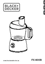
FX400B
Brand: Black & Decker Pages: 24

FX1050
Brand: Black & Decker Pages: 20

MFP200T
Brand: Black & Decker Pages: 12
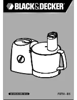
FX710 - B5
Brand: Black & Decker Pages: 32

Power Pro FP2500C
Brand: Black & Decker Pages: 19

PowerPro II FP1611SCKT
Brand: Black & Decker Pages: 16
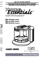
Home Essentials HC21
Brand: Black & Decker Pages: 9

FX800
Brand: Black & Decker Pages: 26

FP800
Brand: Black & Decker Pages: 28

HandyChopper Plus HC3000
Brand: Black & Decker Pages: 12

QuickN'Easy FP1200 Series
Brand: Black & Decker Pages: 24

MultiPREP Slice 'N Dice SL3000
Brand: Black & Decker Pages: 32

Power Pro FP2650S
Brand: Black & Decker Pages: 37

HB5500 Handiprep Express
Brand: Black & Decker Pages: 52

FX1200
Brand: Black & Decker Pages: 20

FX400
Brand: Black & Decker Pages: 28


