Installation Guide:
for the Warmup
Tempo
Digital Programmable Thermostat
Part of the Element Series
Introduction
The
Tempo
thermostat is designed to aid in the comfort of your home by providing timed regulation of your Warmup
underfloor heating system. The thermostat is designed to receive temperature input signals from the following sensors:
1. Air sensor located inside the thermostat
2. Floor sensor installed in the floor to be heated (see Warmup heater instructions for details)
The thermostat is not a safety device and should only be used with Warmup heating products. In order to avoid damaging
your flooring the correct floor type must be selected during the thermostat programming process.
Electrical Specification
:
•
Supply voltage: 230V +/-15% at 50Hz
•
Thermostat is not designed for use with intermittent power supply.
•
Maximum Switch Load: 16A resistive
•
Insulation Class : II
•
Housing : IP20
•
Sensor NTC : 10K @ 25°C
•
Standards: EN60730-1 & EN60730-2-9
•
Meets LVD and EMC directives for safety and electromagnetic compatibility
WARNING – Important safety note
This product uses mains voltage electricity and work should only be carried out by a qualified electrician. You should always
isolate the power supply before attempting to install or repair the
Tempo
thermostat. The thermostat should not be put into
operation unless you are certain that the entire heating installation complies with current general safety requirements for
electrical installations. Electrical installation must be in accordance with the latest IEE Wiring Regulations and appropriate
Statutory Regulations.
The thermostat should be installed inside a single gang electrical wall box that is at least 32mm deep. For optimal
performance, the thermostat should be located in an area with good ventilation. It should not be installed beside a drafty
window/door, in direct sunlight or above another heat generating device (e.g. Radiator or TV).
The thermostat is designed for operation between 0°C and 50°C with relative humidity less than 80%.
Location and installation of floor sensor
The optimum location of the floor sensor is described in each Warmup heater installation manual. Refer to that manual when
selecting floor sensor location.
Warmup recommend the use of conduit when installing the floor sensor. The conduit will protect the sensor and will allow
easier repair of the sensor in the case of sensor damage after flooring has been laid.
Installation:
Separate the front housing of thermostat from the wall module:
1. Unscrew both closing screws (bottom of thermostat) until they will not turn any further.
2. Release front housing by gripping the lower half of outer frame and pulling outwards
then upwards.
3. Place front housing somewhere safe.
4. Run all wires to the wall box. Check to ensure that you have included the following:
•
Power (Live and Neutral)
•
Heater (Live and Neutral)
•
Floor sensor
•
Fil pilote (France only)
5. Pull wires through the wall box and complete terminal wiring.
IMPORTANT:
Ensure that multi strand wires are fully inserted into the terminal and secured
tightly.
Any loose strands should be trimmed as they could cause a short-circuit.
If connecting more than two heaters, an electrical junction box will be required.
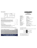
Thermostat location
1
2
3
4
ELT-01-XX-01 - Installation guide V1.1 © Warmup plc - 2014